Electronic Project Notes
Must Watch!
PlatformIO
PlatformIO for Arduino, ESP8266, and ESP32 Tutorial
Peripheral Interface
i2c-bus
introduction to spi
i2c-bus Only two bus lines are required
No strict baud rate requirements
Simple master/slave relationships exist between all components
Each device connected to the bus is software-addressable by a unique address
true multi-master bus providing arbitration and collision detection
SPI synchronous, full duplex master-slave-based interface. The data from the master or the slave is synchronized on the rising or falling clock edge.
Both master and slave can transmit data at the same time.
The SPI interface can be either 3-wire or 4-wire.
SPI devices support much higher clock frequencies compared to I2C interfaces
The chip select signal from the master is used to select the slave.
红外体温测量方案
红外体温测量方案
Contactless CPU Card and Contactless IC Card
Contactless CPU Card And Contactless IC Card
plastic pvc cards
RFID Card CPU Card
The contactless IC card is also called a logical encryption card or a memory card.
The integrated circuit in the card has encryption logic and EEPROM (Electrically Erasable Programmable Read Only Memory).
The logical encryption card has a storage IC card that prevents the information in the card from being arbitrarily rewritten.
When the encryption card is operated, the password in the card must be checked first.
Only when the check is correct and a correct response signal is sent from the card, the card can be performed.
The correct operation, but because only one authentication, and no other security measures, it is easy to lead to password leakage and the generation of fake cards, its security performance is very low.
For example, common non-contact IC cards include X50's Mifare One series S50 and S70, and domestic Fudan FM1108.
These cards are currently widely used in the market.
The contactless logic encryption card technology has been quickly favored by the users with its low cost, concise transaction process and simpler system architecture.
With the continuous application process of the contactless logic encryption card, the contactless logic encryption card technology The inadequacies are also increasingly exposed.
The criminals can use the technical loophole method to recharge and copy non-contact IC chips at low cost, such as illegally recharging or copying all kinds of "one card" and access cards, which brings great social security risks.
Therefore, the non-contact CPU card smart card technology is becoming a technically updated option.
The contactless CPU card is also called a smart card.
The integrated circuit in the card includes a central processing unit (CPU), an EEPROM, a random access memory (ROM), and an on-chip operating system (COS) that is solidified in a read only memory (ROM).
The in-card chip also integrates an encryption computing coprocessor to improve security and speed, making its specifications far higher than logical encryption cards.
The contactless CPU card has a micro-processing function, which is far superior to the logical encryption card in terms of transaction speed and data interference, and allows multiple cards to operate simultaneously, and has an anti-collision mechanism.
Compared with non-contact IC cards, non-contact CPU card smart cards have independent CPU processors and chip operating systems, so they can more flexibly support a variety of different application requirements and design transaction processes more securely.
At the same time, compared with the non-contact IC card system, the system of the contactless CPU card smart card is more complicated, and more system modifications, such as key management, transaction process, PSAM card and card personalization, are required.
Keys are usually divided into recharge key (ISAM card), depreciation key (PSAM card), identity authentication key (SAM card, non-contact CPU card smart card can pass internal and external authentication mechanisms, such as electronic as defined by the Ministry of Construction The transaction process of the wallet is highly reliable to meet the security and key management requirements of different business processes.
For the electronic wallet, the storage key can be used, the consumption can use the consumption key, and the clearing can use the TAC key to update the data.
The card application maintenance key can be used, and the card transfer key, the card master key, the application master key, etc.
can be used in the card personalization process, and the key is used.
The contactless CPU card smart card can be used.
The key version mechanism, that is, for different batches of user cards, use different versions of keys to coexist in the system, achieve the purpose of natural expiration of key expiration, gradually replace the keys used in the system, and prevent the system from being long-term.
The security risks brought by the use, non-contact CPU card smart card, can also use the key index mechanism, that is, for the issued user card, support multiple groups at the same time The key that is introduced, if the currently used key is leaked or there is a security risk, the system can urgently activate the key of another set of indexes without recycling and replacing the card on the user's hand.
Therefore, with the non-contact IC card Compared with the system, the contactless CPU card smart card system supports a wider range of functions, and is more flexible, secure and complex.
The contactless CPU card is inferior to the non-contact IC card in terms of fast transaction speed, which is also the non-contact IC card technology.
An important reason for widespread use.
However, the unilateral pursuit of transaction speed, even at the expense of security, is an infallible practice.
Because there is no reliable security, it loses the use of IC card technology, especially non-contact CPU cards.
At the same time, security often consumes a certain amount of transaction time and reduces the speed of transactions.
The above is about the difference between contactless CPU card and contactless IC card from non-contact CPU card and non- The characteristics of the contact IC card and the perspective of the application requirements are briefly introduced.
For the contradiction between security and transaction speed, The designer of the system should find the balance between the two according to the actual business needs, and we should consider your actual situation.
The demand and various factors, fully do the technical certification and planning and design of the system transformation, and effectively study many technical problems in the implementation process, is an important prerequisite and guarantee for the success of the project.
Plastic Key Cards
PVC badges
Gift Cards
Loyalty Cards
Discount Cards
Event passes
Employee/Photo/Portrait ID Cards
Membership/VIP Cards
Carbon fiber cards
Plastic Business/Name Cards
Plastic Key Tags
Plastic Luggage Tags
Hanger tags
PVC Plastic Rulers
Key tag/snap-off key tags
Other Plastic Cards
Plastic Cards Options
Barcode Cards
Custom Die Cutting Cards
Embossed Cards
Frosted Cards
Hologram Cards
Magnetic Stripe Cards
Metallic Cards
QR Code Cards
Scratch off Cards
Spot UV Cards
Transparent/Clear Plastic Cards
Other Plastic Cards Options
Blocking Cards
Smart Cards
3D Cards
Chest Badges
Paper Cards
物聯網的優勢
物聯網的優勢在於通過傳感器等收集和分析大量數據,飛躍式提高業務效率。

Electronic Open Source Projects
SG90, MG90 best 10 SG90 projects
OPEN SOURCE PROJECTS
Open Source SG90 Micro Servo Motor Projects
Servo Tutorial
sparkfun learn
sparkfun tutorials
Control Servos using Arduino
Arduino tutorials
Control Servo motor using ESP32
ESP32 Servo Motor Web Server
control Servo Motor using ESP32
Using Servo Motors - SG90
esp32 micro servo
ESP32 Servo Motor Web Server
Using Servo Motors with ESP32
MicroPython libraries
MicroPython provides built-in modules that mirror the functionality of the Python standard library (e.g. os, time), as well as MicroPython-specific modules (e.g. bluetooth, machine).
Most Python standard library modules implement a subset of the functionality of the equivalent Python module, and in a few cases provide some MicroPython-specific extensions (e.g. array, os)
Due to resource constraints or other limitations, some ports or firmware versions may not include all the functionality documented here.
To allow for extensibility, some built-in modules can be extended from Python code loaded onto the device filesystem.
This chapter describes modules (function and class libraries) which are built into MicroPython.
This documentation in general aspires to describe all modules and functions/classes which are implemented in the MicroPython project.
However, MicroPython is highly configurable, and each port to a particular board/embedded system may include only a subset of the available MicroPython libraries.
With that in mind, please be warned that some functions/classes in a module (or even the entire module) described in this documentation may be unavailable
in a particular build of MicroPython on a particular system.
The best place to find general information of the availability/non-availability of a particular feature is the “General Information” section which contains information pertaining to a specific MicroPython port.
On some ports you are able to discover the available, built-in libraries that can be imported by entering the following at the REPL:
help('modules')
Beyond the built-in libraries described in this documentation, many more modules from the Python standard library, as well as further MicroPython extensions to it, can be found in micropython-lib.
Python standard libraries and micro-libraries
The following standard Python libraries have been “micro-ified” to fit in with the philosophy of MicroPython.
They provide the core functionality of that module and are intended to be a drop-in replacement for the standard Python library.
array – arrays of numeric data
asyncio — asynchronous I/O scheduler
binascii – binary/ASCII conversions
builtins – builtin functions and exceptions
cmath – mathematical functions for complex numbers
collections – collection and container types
errno – system error codes
gc – control the garbage collector
gzip – gzip compression & decompression
hashlib – hashing algorithms
heapq – heap queue algorithm
io – input/output streams
json – JSON encoding and decoding
math – mathematical functions
os – basic “operating system” services
platform – access to underlying platform’s identifying data
random – generate random numbers
re – simple regular expressions
select – wait for events on a set of streams
socket – socket module
ssl – SSL/TLS module
struct – pack and unpack primitive data types
sys – system specific functions
time – time related functions
zlib – zlib compression & decompression
_thread – multithreading support
MicroPython-specific libraries
Functionality specific to the MicroPython implementation is available in the following libraries.
bluetooth — low-level Bluetooth
btree – simple BTree database
cryptolib – cryptographic ciphers
deflate – deflate compression & decompression
framebuf — frame buffer manipulation
machine — functions related to the hardware
micropython – access and control MicroPython internals
neopixel — control of WS2812 / NeoPixel LEDs
network — network configuration
uctypes – access binary data in a structured way
The following libraries provide drivers for hardware components.
WM8960 – Driver for the WM8960 codec
Port-specific libraries
In some cases the following port/board-specific libraries have functions or classes similar to those in the machine library.
Where this occurs, the entry in the port specific library exposes hardware functionality unique to that platform.
To write portable code use functions and classes from the machine module.
To access platform-specific hardware use the appropriate library, e.g. pyb in the case of the Pyboard.
Libraries specific to the ESP8266 and ESP32
The following libraries are specific to the ESP8266 and ESP32.
esp — functions related to the ESP8266 and ESP32
Functions
esp32 — functionality specific to the ESP32
Functions
Flash partitions
RMT
Constants
Ultra-Low-Power co-processor
Constants
Non-Volatile Storage
espnow — support for the ESP-NOW wireless protocol
Extending built-in libraries from Python
A subset of the built-in modules are able to be extended by Python code by providing a module of the same name in the filesystem.
This extensibility applies to the following Python standard library modules which are built-in to the firmware: array, binascii, collections, errno, gzip,
hashlib, heapq, io, json, os, platform, random,
re, select, socket, ssl, struct, time zlib, as well as the MicroPython-specific machine module.
All other built-in modules cannot be extended from the filesystem.
This allows the user to provide an extended implementation of a built-in library
(perhaps to provide additional CPython compatibility or missing functionality).
This is used extensively in micropython-lib, see Package management for more information.
The filesystem module will typically do a wildcard import of the built-in module in order to inherit all the globals (classes, functions and variables) from the built-in.
In MicroPython v1.21.0 and higher, to prevent the filesystem module from importing itself, it can force an import of the built-in module it by temporarily clearing sys.path during the import.
For example, to extend the
time module from Python, a file named time.py on the filesystem would do the following:
_path = sys.path sys.path = ()
try:
from time import *
finally:
sys.path = _path
del _path
def extra_method():
pass
The result is that time.py contains all the globals of the built-in time
module, but adds extra_method.
In earlier versions of MicroPython, you can force an import of a built-in module by appending a u to the start of its name.
For example, import utime
instead of import time.
For example, time.py on the filesystem could look like:
from utime import *
def extra_method():
pass
This way is still supported, but the sys.path method described above is now preferred as the u-prefix will be removed from the names of built-in modules in a future version of MicroPython.
Other than when it specifically needs to force the use of the built-in module,
code should always use import module rather than import umodule.
ESP32 Bluetooth Getting started
ESP32 has on-chip Bluetooth and BLE (Bluetooth Low Energy).
In this guide, we will see the Bluetooth part.
ESP32 Bluetooth is also referred as classic Bluetooth.
Using Bluetooth is very much simple on ESP32 with BluetoothSerial Library with Arduino IDE.
To start with, open the example in Arduino IDE File > Examples > BluetoothSerial > SerialtoSerialBT.
//This example code is in the Public Domain (or CC0 licensed, at your option.)
//By Evandro Copercini - 2018
//
//This example creates a bridge between Serial and Classical Bluetooth (SPP)
//and also demonstrate that SerialBT have the same functionalities of a normal Serial
#include "BluetoothSerial.h"
#if !defined(CONFIG_BT_ENABLED) || !defined(CONFIG_BLUEDROID_ENABLED)
#error Bluetooth is not enabled! Please run `make menuconfig` to and enable it
#endif
BluetoothSerial SerialBT;
void setup() {
Serial.begin(115200);
SerialBT.begin("ESP32test"); //Bluetooth device name
Serial.println("The device started, now you can pair it with bluetooth!");
}
void loop() {
if (Serial.available()) {
SerialBT.write(Serial.read());
}
if (SerialBT.available()) {
Serial.write(SerialBT.read());
}
delay(20);
}
How this code works
The code starts with
#include "BluetoothSerial.h"
The next three lines check if Bluetooth is properly enabled.
#if !defined(CONFIG_BT_ENABLED) || !defined(CONFIG_BLUEDROID_ENABLED)
#error Bluetooth is not enabled! Please run `make menuconfig` to and enable it
#endif
Now, we have to define the object of the class BluetoothSerial.
This object will be used for initializing the Bluetooth Stack on ESP32.
Defining the Object:
BluetoothSerial SerialBT;
setup()
In the setup initialize serial communication at a baud rate of 115200.
Next, we call the begin function of the BluetoothSerial object.
This will initialize the Bluetooth Serial.
As an input to this function, we pass the name which we want to assign to the Bluetooth.
Here is “ESP32test”.
SerialBT.begin("ESP32test"); //Bluetooth device name
loop()
In the loop, we send and receive the data via Bluetooth Serial.
First if statement: we check if bytes are being received in the serial port.
In this example, we will send the data from Computer to ESP32 on Serial Communication.
If this data is available, then send that information via Bluetooth to the connected device.
i.e., Smartphone.
if (Serial.available()) {
SerialBT.write(Serial.read());
}
SerialBT.write() sends data using Bluetooth serial to the connected device.
Serial.read() returns the data received in the serial port.
The next if statement, checks if there are bytes available to read in the Bluetooth Serial port.
If there are, we’ll write those bytes in the Serial Monitor on the computer.
if (SerialBT.available()) {
Serial.write(SerialBT.read());
}
Testing on ESP32
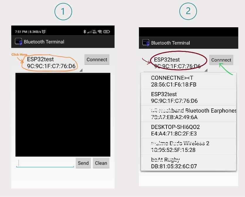
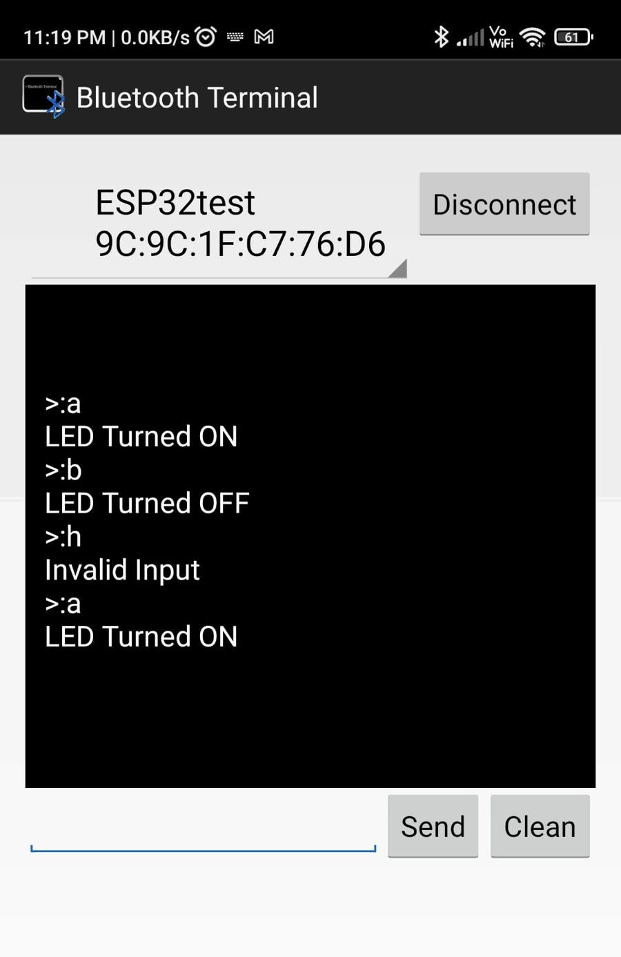
First, we need Android Smartphone, where we have to download app on Google Play Store for Bluetooth serial Terminal.
There are multiple apps available.
You can download any.
I will suggest the following, “Bluetooth Terminal” it’s light and simple.
Install it.
Now Upload the code in Your ESP32 Board.
The code will start executing and Turns ON the ESP32 Bluetooth Stack.
Now go to your Android Phone Bluetooth Setting >> search for new device
You will find the Device with the name “ESP32test”.
Click on it and add it to the pair device.
After successfully paring, Open the “Bluetooth Terminal” Application, and connect to the “ESP32test”.
Screenshot as follow:
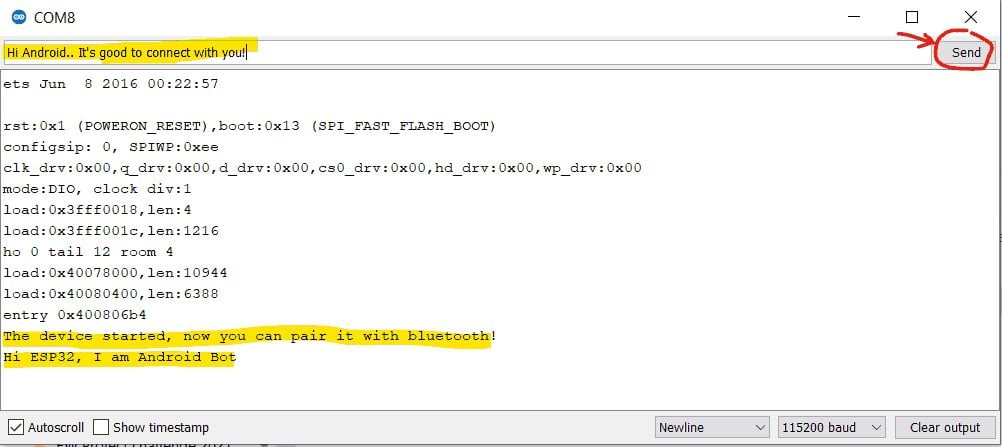
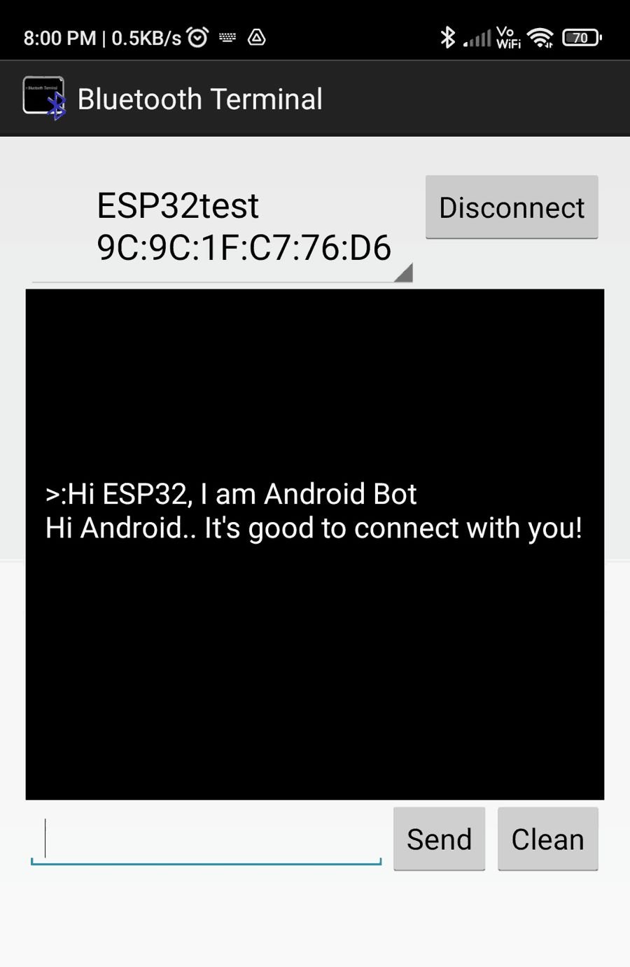
 After connecting with the ESP32test, we can type the string and send it to ESP32.
Also, we can send a string to our Smartphone via ESP32 Bluetooth.
After connecting with the ESP32test, we can type the string and send it to ESP32.
Also, we can send a string to our Smartphone via ESP32 Bluetooth.
Output on Serial Monitor
Bluetooth Terminal App Output
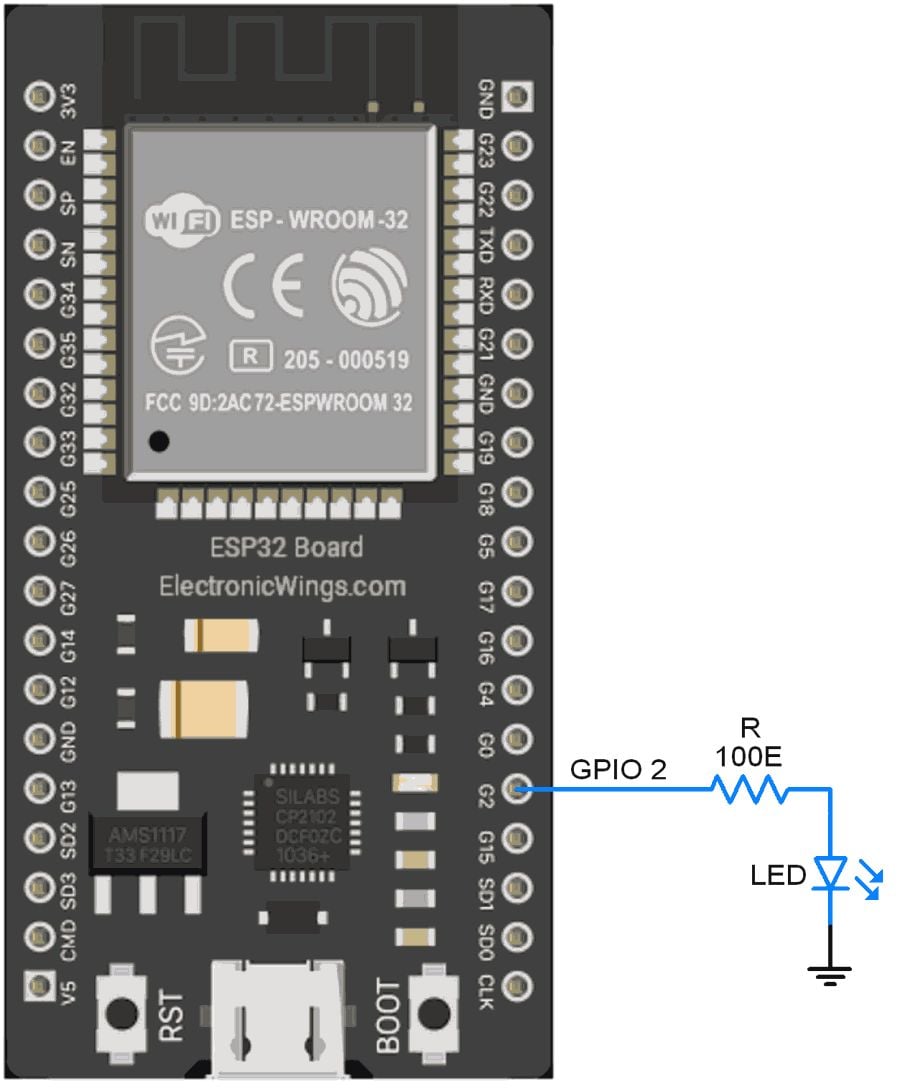
Control the LED using the ESP32 Bluetooth Application
Turning LED ON and OFF using ESP32 Bluetooth.
Interfacing diagram
 /*
Controlling LED/GPIO using Bluetooth
http:://www.electronicwings.com
*/
#include "BluetoothSerial.h"
const char LED= 2;
const char turnON ='a';
const char turnOFF ='b';
#if !defined(CONFIG_BT_ENABLED) || !defined(CONFIG_BLUEDROID_ENABLED)
#error Bluetooth is not enabled! Please run `make menuconfig` to and enable it
#endif
BluetoothSerial SerialBT;
void setup() {
Serial.begin(115200);
pinMode(LED, OUTPUT);
SerialBT.begin("ESP32test"); //Bluetooth device name
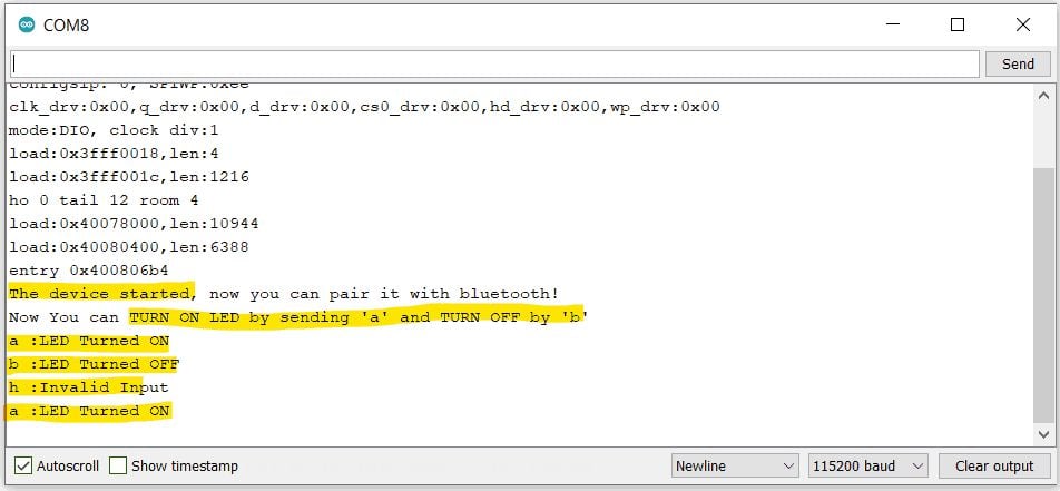
Serial.println("The device started, now you can pair it with bluetooth!");
Serial.println("Now You can TURN ON LED by sending 'a' and TURN OFF by 'b'");
}
void loop() {
char message;
if (SerialBT.available()) {
message=SerialBT.read();
Serial.write(message);
if(message==turnON){
digitalWrite(LED, HIGH); //Turn LED ON
Serial.println(" :LED Turned ON");
SerialBT.println("LED Turned ON");
}
else if(message==turnOFF){
digitalWrite(LED, LOW); //Turn LED Off
Serial.println(" :LED Turned OFF");
SerialBT.println("LED Turned OFF");
}
else{
Serial.println(" :Invalid Input");
SerialBT.println("Invalid Input");
}
}
delay(20);
}
/*
Controlling LED/GPIO using Bluetooth
http:://www.electronicwings.com
*/
#include "BluetoothSerial.h"
const char LED= 2;
const char turnON ='a';
const char turnOFF ='b';
#if !defined(CONFIG_BT_ENABLED) || !defined(CONFIG_BLUEDROID_ENABLED)
#error Bluetooth is not enabled! Please run `make menuconfig` to and enable it
#endif
BluetoothSerial SerialBT;
void setup() {
Serial.begin(115200);
pinMode(LED, OUTPUT);
SerialBT.begin("ESP32test"); //Bluetooth device name
Serial.println("The device started, now you can pair it with bluetooth!");
Serial.println("Now You can TURN ON LED by sending 'a' and TURN OFF by 'b'");
}
void loop() {
char message;
if (SerialBT.available()) {
message=SerialBT.read();
Serial.write(message);
if(message==turnON){
digitalWrite(LED, HIGH); //Turn LED ON
Serial.println(" :LED Turned ON");
SerialBT.println("LED Turned ON");
}
else if(message==turnOFF){
digitalWrite(LED, LOW); //Turn LED Off
Serial.println(" :LED Turned OFF");
SerialBT.println("LED Turned OFF");
}
else{
Serial.println(" :Invalid Input");
SerialBT.println("Invalid Input");
}
}
delay(20);
}
Output on Serial Monitor
Bluetooth Terminal App Output
How this code Works
Once we turn ON the Bluetooth, the code scans for any data available on the Bluetooth serial.
if (SerialBT.available())
Then simply, if the character received is ‘a’, the Code will Turn ON the LED.
Also, it will send the action “LED Turned ON” to the Bluetooth device and computer terminal as well.
If the Character received is ‘b’, the Code will Turn OFF the LED.
If any other character is received, it will be considered invalid.
Directly Connect ESP32 BLE with Mobile Bluetooth using Micropython
Programming the ESP32 with MicroPython
Programming the ESP32 with MicroPython
Pinout of the ESP32
I have explained the pins of the ESP32 and their functions in detail here.
The pinout is:
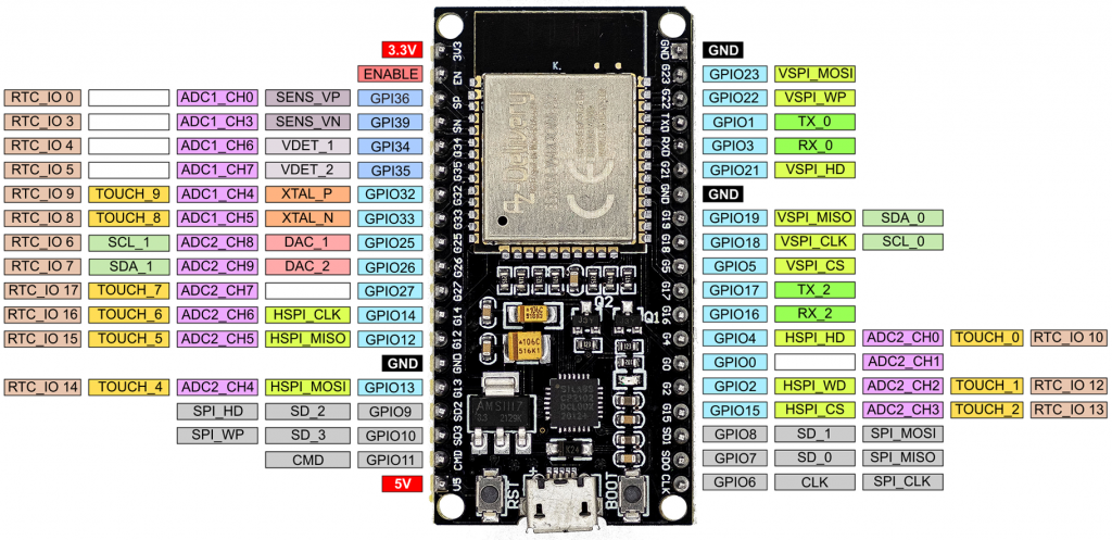 Pinout of the ESP32 with MicroPython
The only difference to the pin assignment in the Arduino implementation is the position of the I2C pins.
Pinout of the ESP32 with MicroPython
The only difference to the pin assignment in the Arduino implementation is the position of the I2C pins.
Short repetition: Switching and reading the GPIOs
A simple blink program on the ESP32 with MicroPython looks like this:
blink.py
from machine import Pin
from time import sleep
led = Pin(18, Pin.OUT)
while True:
led.value(not led.value())
sleep(0.5)
from machine import Pin
from time import sleep
led = Pin(18, Pin.OUT)
while True:
led.value(not led.value())
sleep(0.5)
from machine import Pin
from time import sleep
led = Pin(18, Pin.OUT)
while True:
led.value(not led.value())
sleep(0.5)
The big difference to C++ is that the pins are defined as objects.
Whether a pin acts as input or output is determined with Pin.OUT or Pin.IN.
You can read the GPIO level with pinname.value().
You can switch the pin using pinname.value(0/1).
In addition, you can connect internal pull-up or pull-down resistors if they are available at the respective pin.
You would define a pin for reading a button state like this:
buttonPin = Pin(18, Pin.IN, Pin.PULL_DOWN) # button Pin = GPIO18
buttonPin = Pin(18, Pin.IN, Pin.PULL_DOWN) # button Pin = GPIO18
Read the ADCs of the ESP32 with MicroPython
First of all: As powerful as the ESP32 is, as bad are its A/D converters.
They generate quite a bit of noise, and what’s worse, they are not linear.
I have described this in detail here.
Now for the code:
from machine import ADC, Pin
from time import sleep
adc = ADC(Pin(32))
adc.atten(ADC.ATTN_11DB) # ATTN_11DB, ATTN_6DB, ATTN_2_5DB, ATTN_0DB (default)
adc.width(ADC.WIDTH_12BIT) # WIDTH_12BIT (default), WITDTH_11BIT, WIDTH_10BIT, WIDTH_9BIT
while True:
val = adc.read()
print("Raw ADC value:", val)
sleep(1)
In order to use a pin as an A/D converter input, you first create an object.
The default resolution is 12 bits.
Alternatively, you can set with adc.width() 11, 10 or 9 bits.
With adc.atten(ADC.ATTN_XDB) you set the attenuation and thus determine the input voltage range:
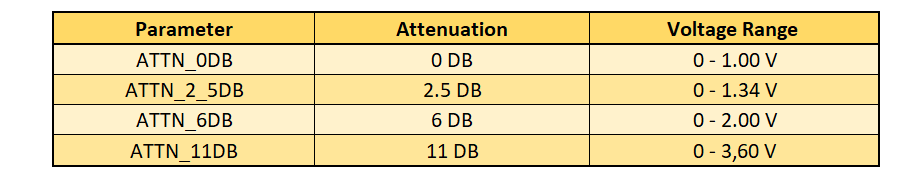 Parameter selection for attenuation
This data is from the MicroPython Quick Reference.
In my own measurements, the A/D converter overflowed in the maximum range at about 3.15 volts.
Parameter selection for attenuation
This data is from the MicroPython Quick Reference.
In my own measurements, the A/D converter overflowed in the maximum range at about 3.15 volts.
Pulse width modulation
To produce pulse width modulation (PWM), you create a PWM object for a specific pin and pass the frequency and duty cycle.
With the Arduino implementation of the ESP32 you can set the resolution (see here).
If you program the ESP32 with MicroPython, only 10 bit resolution is available (0-1023).
Here is an example:
pwm.py
from machine import Pin, PWM
pwm16 = PWM(Pin(16)) # create PWM object from GPIO 16
pwm16.freq(1000) # 1 kHz
pwm16.duty(256) # duty cycle = 256/1024 * 100 = 25%
# pwm16 = PWM(Pin(16), freq=1000, duty=256) # short Version
from machine import Pin, PWM
pwm16 = PWM(Pin(16)) # create PWM object from GPIO 16
pwm16.freq(1000) # 1 kHz
pwm16.duty(256) # duty cycle = 256/1024 * 100 = 25%
# pwm16 = PWM(Pin(16), freq=1000, duty=256) # short Version
from machine import Pin, PWM
pwm16 = PWM(Pin(16)) # create PWM object from GPIO 16
pwm16.freq(1000) # 1 kHz
pwm16.duty(256) # duty cycle = 256/1024 * 100 = 25%
# pwm16 = PWM(Pin(16), freq=1000, duty=256) # short Version
Other functions are:
pwm16.freq() # get current frequency
pwm16.duty() # get current duty cycle
pwm16.deinit() # turn off PWM on the pin
pwm16.freq() # get current frequency
pwm16.duty() # get current duty cycle
pwm16.deinit() # turn off PWM on the pin
pwm16.freq() # get current frequency
pwm16.duty() # get current duty cycle
pwm16.deinit() # turn off PWM on the pin
The maximum PWM frequency is 40 MHz.
However, due to the timer frequency of the ESP32 (80 MHz), you only get the full 10 bit resolution up to the following PWM frequency:
fmax, full res=21080000000=78125[Hz]
For larger frequencies, you can calculate the actual resolution as follows:
res=f80000000
For example, if you choose 20 MHz as frequency, you only have a resolution of 4, i.e.
you can set the duty cycles 0, 25, 50 and 75% by passing values in the ranges 0-255, 256-511, 512-767 or 768-1023 to pwm.duty().
Analog Pins
You can pick off a real analog signal between 0 and 3.3 V at pins 25 and 26.
The resolution is 8 bits.
Here’s how it works:
dac.py
from machine import Pin, DAC
dac = DAC(Pin(25))
dac.write(128) # voltage = 3.3 * 128/256
from machine import Pin, DAC
dac = DAC(Pin(25))
dac.write(128) # voltage = 3.3 * 128/256
from machine import Pin, DAC
dac = DAC(Pin(25))
dac.write(128) # voltage = 3.3 * 128/256
The drawback: the output voltage is linear to the value passed to dac.write(), but the slope of the straight line is not quite right.
In my measurements, the range was 0.086 to 3.18 volts instead of 0 to 3.3 volts (see
Time functions
The equivalents to delay() and delayMicroseconds() when using ESP32 with MicroPython are sleep_ms() or sleep_us().
In addition, you can use sleep() which takes seconds as parameter.
millis() and micros() are called ticks_ms() and ticks_us() in MicroPython.
With ticks_diff() you can determine time spans.
Here is a small example:
import time
start_ms = time.ticks_ms()
start_us = time.ticks_us()
print("Millisecs: ", start_ms)
print("Microsecs: ", start_us)
time.sleep(3)
delta = time.ticks_diff(time.ticks_ms(), start_ms)
print("Delta =", delta)
import time
start_ms = time.ticks_ms()
start_us = time.ticks_us()
print("Millisecs: ", start_ms)
print("Microsecs: ", start_us)
time.sleep(3)
delta = time.ticks_diff(time.ticks_ms(), start_ms)
print("Delta =", delta)
import time
start_ms = time.ticks_ms()
start_us = time.ticks_us()
print("Millisecs: ", start_ms)
print("Microsecs: ", start_us)
time.sleep(3)
delta = time.ticks_diff(time.ticks_ms(), start_ms)
print("Delta =", delta)
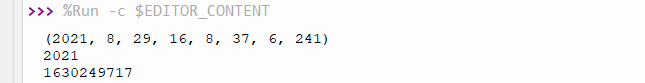
The time module
With the time module, you can query the current time and the seconds since 01/01/2000, 00:00 o’clock.
You can calculate the frequently used Unix time from this.
local_and_unixtime.py
import time
now = time.localtime() # query local time as tuple
print(now)
print(now[0]) # print element 0
now_secs = time.time() # secs since 01/01/2000, 00:00
now_unix = now_secs + 946681200 # unixtime: secs since 01/01/1970, 00:00
print(now_unix)
import time
now = time.localtime() # query local time as tuple
print(now)
print(now[0]) # print element 0
now_secs = time.time() # secs since 01/01/2000, 00:00
now_unix = now_secs + 946681200 # unixtime: secs since 01/01/1970, 00:00
print(now_unix)
import time
now = time.localtime() # query local time as tuple
print(now)
print(now[0]) # print element 0
now_secs = time.time() # secs since 01/01/2000, 00:00
now_unix = now_secs + 946681200 # unixtime: secs since 01/01/1970, 00:00
print(now_unix)
“localtime” is used as a tuple in the format:
(year, month, day of the month, hours, minutes, seconds, day of the week, day of the year)
The elements are integers.
Here’s what the output looks like:
 Output of local_and_unixtime.py
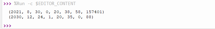
The RTC class
If you want to set the date and time of the ESP32, then you have to use the RTC class.
The time tuple is structured a little differently:
(year, month, day of the month, day of the week, hours, minutes, seconds, microseconds).
On the day of the week, it should be noted that Monday is 0 and Sunday is 6.
When setting the time, the day of the week is irrelevant.
MicroPython will correct the day of the week if it is wrong.
from machine import RTC
rtc = RTC()
a = rtc.datetime()
print(a)
new_time= (2030, 12, 24, 0, 20, 35, 0, 0)
rtc.init(new_time)
a = rtc.datetime()
print(a)
from machine import RTC
rtc = RTC()
a = rtc.datetime()
print(a)
new_time= (2030, 12, 24, 0, 20, 35, 0, 0)
rtc.init(new_time)
a = rtc.datetime()
print(a)
from machine import RTC
rtc = RTC()
a = rtc.datetime()
print(a)
new_time= (2030, 12, 24, 0, 20, 35, 0, 0)
rtc.init(new_time)
a = rtc.datetime()
print(a)
 In addition, we learn: the time is set according to the system time of the computer when booting the ESP32.
Actually, the RTC class can do much more, e.g.
alarm interrupts.
However, this does not seem to have been implemented (yet) for the ESP32.
In addition, we learn: the time is set according to the system time of the computer when booting the ESP32.
Actually, the RTC class can do much more, e.g.
alarm interrupts.
However, this does not seem to have been implemented (yet) for the ESP32.
External interrupts
External (pin change) interrupts can be set up for each GPIO.
This works similarly to the Arduino.
The following program triggers an interrupt when a button attached to GPIO 23 is pressed.
An LED on the GPIO 18 then lights up:
interrupt.py
from machine import Pin
from time import sleep
led = Pin(18, Pin.OUT)
btn = Pin(23, Pin.IN, Pin.PULL_DOWN)
btn_pressed = False
def btn_handler(btn):
global btn_pressed
btn_pressed = True
btn.irq(trigger=Pin.IRQ_RISING, handler=btn_handler)
while True:
if btn_pressed:
led.value(1)
sleep(1)
led.value(0)
btn_pressed = False
A few explanations:
- With btn.irq() the pin “btn” gets an interrupt function.
- trigger=Pin.IRQ_RISING causes the interrupt to be triggered by the rising edge.
- In addition, there is – surprise! – also IRQ_FALLING.
- handler=btn_handler defines the interrupt handler, i.e.
the function that is called when the interrupt is triggered (without parentheses).
- You must pass the pin object to the interrupt handler.
- In the handler function, btn_pressed must be set as global, otherwise Python considers the variable to be local.
Programming the timers of the ESP32 with MicroPython
Timers trigger internal interrupts.
The ESP32 has 4 hardware timers with the ID 0 to 3, and they are easy to program.
No comparison to the timers of the ATmega328P! Here is an example program that flashes 2 LEDs in asynchronously:
timer.py
from machine import Pin, Timer
led0 = Pin(18, Pin.OUT)
led1 = Pin(19, Pin.OUT)
def handler_0(tim0):
led0.value(not led0.value())
def handler_1(tim1):
led1.value(not led1.value())
tim0 = Timer(0)
tim0.init(period=973, mode=Timer.PERIODIC, callback=handler_0)
tim1 = Timer(1)
tim1.init(period=359, mode=Timer.PERIODIC, callback=handler_1)
I think the code is almost self-explanatory:
- Timer is a class of the machine module.
- First you create a timer object and pass the timer ID (0 to 3).
- init() expects three arguments:
- period is the timespan in milliseconds until the timer interrupt is triggered.
- mode is either PERIODIC or ONE_SHOT.
- callback defines the function (interrupt handler) that will be called when the timer interrupt is triggered.
- As with external interrupts, you must pass the causing object to the handlers (tim0 and tim1 in this case).
Isn’t that wonderfully easy?
As an alternative to periods, you can also pass the frequency in Hertz, e.g.: freq = 20000.
Watchdog timer
The watchdog timer of the ESP32 is not particularly convenient, but easy to program.
You create a WDT object and pass the timeout in milliseconds.
Once started, it can no longer be stopped.
It’s a bit unusual that you can only prevent the reset by a wdt.feed().
Other MCUs extend the timeout with any statement.
Here is an example:
wdt.py
from machine import WDT
from time import sleep
wdt = WDT(timeout=5000)
print("Hi, I have just booted")
while True:
sleep(1)
print("Still there...")
#wdt.feed()
from machine import WDT
from time import sleep
wdt = WDT(timeout=5000)
print("Hi, I have just booted")
while True:
sleep(1)
print("Still there...")
#wdt.feed()
from machine import WDT
from time import sleep
wdt = WDT(timeout=5000)
print("Hi, I have just booted")
while True:
sleep(1)
print("Still there...")
#wdt.feed()
You will see that the ESP32 resets after 5 seconds.
If you uncomment wdt.feed(), that doesn’t happen.
By the way, the minimum timeout is 1 second.
I2C
The ESP32 has two I2C interfaces.
I had explained this in detail here.
In MicroPython, the interfaces are distinguished by their index (0 or 1).
Interface 0 is assigned to GPIOs 18 (SCL) and 19 (SDA).
Interface 1 is assigned to GPIOs 25 (SCL) and 26 (SDA).
You can change the assignment and optionally specify the frequency. You do this when you create your I2C object.
i2c_definition.py
from machine import I2C, Pin # I2C is a class in machine
i2c = I2C(0) # simplest definition, SDA=GPIO19, SCL=GPIO18
i2c = I2C(1) # SDA=GPIO26, SCL=GPIO25
i2c = I2C(0, scl=Pin(16), sda=Pin(17)) # new pin assignment
i2c = I2C(1, scl=Pin(12), sda=Pin(14), freq=400000) # new frequency and pin assignment
Scanning for I2C addresses is easy with scan().
The function returns a list of I2C addresses in decimal numbers:
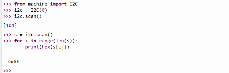 i2c.scan() in action
You write into registers via I2C with the function writeto_mem() and read them with readfrom_mem() or readfrom_mem_into().
You need to pass the I2C address and the register number to these functions.
The data you write or query must be of type bytearray, even if it is only one byte.
Here’s how the functions are used:
# writing to registers:
data = bytearray([128, 255]) # just an example
i2c.writeto_mem(I2C_ADDR, REG_ADDR, data)
# reading from registers:
data = i2c.readfrom_mem(I2C_ADDR, REG_ADDR, 2) # read two bytes
# or, alternatively:
data = bytearray(2)
i2c.readfrom_mem_into(I2C_ADDR, REG_ADDR, data)
# writing to registers:
data = bytearray([128, 255]) # just an example
i2c.writeto_mem(I2C_ADDR, REG_ADDR, data)
# reading from registers:
data = i2c.readfrom_mem(I2C_ADDR, REG_ADDR, 2) # read two bytes
# or, alternatively:
data = bytearray(2)
i2c.readfrom_mem_into(I2C_ADDR, REG_ADDR, data)
# writing to registers:
data = bytearray([128, 255]) # just an example
i2c.writeto_mem(I2C_ADDR, REG_ADDR, data)
# reading from registers:
data = i2c.readfrom_mem(I2C_ADDR, REG_ADDR, 2) # read two bytes
# or, alternatively:
data = bytearray(2)
i2c.readfrom_mem_into(I2C_ADDR, REG_ADDR, data)
You often need to read 16-bit values from two 8-bit registers and then combine the individual values to form an integer.
This can be done as in C++ with shift operators (MSB<<8 | LSB).
int.from_bytes(data, order) is less cryptic.
Data is a bytearray that contains the bytes to be assembled, order is either “big” or “little”.
“big” means that the MSB (Most Significant Byte) is first, with “little” it is at the end.
Then there is a small problem: how can MicroPython know whether the read data is signed or unsigned? With C++ you can specify that.
The answer is: not at all, but you can easily solve this problem.
For example, if you read a 16-bit signed integer((-215) to (+215-1), then the biggest positive value is 32767.
Larger values are misinterpreted and actually negative.
Because of the two’s complement representation, you just need to subtract 65536 (i.e.216).
This applies at least to the current implementation of MicroPython on the ESP32.
There are also Python versions in which you can pass int.from_bytes() to signed=true.
i2c.scan() in action
You write into registers via I2C with the function writeto_mem() and read them with readfrom_mem() or readfrom_mem_into().
You need to pass the I2C address and the register number to these functions.
The data you write or query must be of type bytearray, even if it is only one byte.
Here’s how the functions are used:
# writing to registers:
data = bytearray([128, 255]) # just an example
i2c.writeto_mem(I2C_ADDR, REG_ADDR, data)
# reading from registers:
data = i2c.readfrom_mem(I2C_ADDR, REG_ADDR, 2) # read two bytes
# or, alternatively:
data = bytearray(2)
i2c.readfrom_mem_into(I2C_ADDR, REG_ADDR, data)
# writing to registers:
data = bytearray([128, 255]) # just an example
i2c.writeto_mem(I2C_ADDR, REG_ADDR, data)
# reading from registers:
data = i2c.readfrom_mem(I2C_ADDR, REG_ADDR, 2) # read two bytes
# or, alternatively:
data = bytearray(2)
i2c.readfrom_mem_into(I2C_ADDR, REG_ADDR, data)
# writing to registers:
data = bytearray([128, 255]) # just an example
i2c.writeto_mem(I2C_ADDR, REG_ADDR, data)
# reading from registers:
data = i2c.readfrom_mem(I2C_ADDR, REG_ADDR, 2) # read two bytes
# or, alternatively:
data = bytearray(2)
i2c.readfrom_mem_into(I2C_ADDR, REG_ADDR, data)
You often need to read 16-bit values from two 8-bit registers and then combine the individual values to form an integer.
This can be done as in C++ with shift operators (MSB<<8 | LSB).
int.from_bytes(data, order) is less cryptic.
Data is a bytearray that contains the bytes to be assembled, order is either “big” or “little”.
“big” means that the MSB (Most Significant Byte) is first, with “little” it is at the end.
Then there is a small problem: how can MicroPython know whether the read data is signed or unsigned? With C++ you can specify that.
The answer is: not at all, but you can easily solve this problem.
For example, if you read a 16-bit signed integer((-215) to (+215-1), then the biggest positive value is 32767.
Larger values are misinterpreted and actually negative.
Because of the two’s complement representation, you just need to subtract 65536 (i.e.216).
This applies at least to the current implementation of MicroPython on the ESP32.
There are also Python versions in which you can pass int.from_bytes() to signed=true.
I2C example: Reading the MPU6050 on ESP32 with MicroPython
The following program provides the acceleration values, temperature and gyroscope data of an MPU6050.
The example shows how compact MicroPython code can be.
i2c_MPU6050.py
from machine import I2C
from time import sleep
MPU_ADDR = 0x68
i2c = I2C(0)
i2c.writeto_mem(MPU_ADDR, 0x6B, bytearray([0])) # "wake-up call"
def byteToInt(bytePair):
intVal = int.from_bytes(bytePair, 'big') # "big" = MSB at beginning
if intVal > 32767: # intVal is negative => 2^15
intVal -= 65536
return intVal
while True:
regVal = i2c.readfrom_mem(MPU_ADDR, 0x3B, 14) # Read 14 bytes
print("AccX =", byteToInt(bytearray([regVal[0],regVal[1]])))
print("AccY =", byteToInt(bytearray([regVal[2],regVal[3]])))
print("AccZ =", byteToInt(bytearray([regVal[4],regVal[5]])))
print("Temp =", (byteToInt(bytearray([regVal[6],regVal[7]])))/340.00+36.53)
print("GyrX =", byteToInt(bytearray([regVal[8],regVal[9]])))
print("GyrY =", byteToInt(bytearray([regVal[10],regVal[11]])))
print("GyrZ =", byteToInt(bytearray([regVal[12],regVal[13]])))
print("***************")
sleep(2)
First, the MPU6050 is woken up by writing a zero to its register 0x6B (“Powermanagement 1”).
The measured values are available in fourteen registers, starting from 0x3B, and they are read in one go.
2 bytes each of the bytearray regVal form one of the 7 measured values.
Most of the time, however, you will probably not want to deal with registers and therefore choose external modules.
I come to that now.
Adding external (I2C) modules
First of all, there is a certain confusion of names here.
You will find the terms module, library and package.
In first approximation, the terms mean the same thing.
For many components such as sensors, displays, ADCs, etc., hard-working people have written modules.
To use them, you have to install them in most cases.
If you work with Thonny, then it is best to use the package manager.
Go to Tools → Manage Packages.
Enter the name and search for PyPI.
Select the package, install it, and you can immediately use it.
This is similar to the library management in the Arduino IDE.
Only the handling of example programs is less well solved.
To get them, you have to go to the platforms where the packages are made available.
However, there may also be modules that you cannot find via the package management.
Maybe you programmed them yourself.
In this case, take the file to be included, right-click on it in Thonny and select “Upload to \”.
Then you can use the classes and functions.
uPyCraft does not have a package management.
There, you open the file to be included and select “Download”.
SPI
The ESP32 has four SPI interfaces, of which you can use two.
They are called HSPI and VSPI and they are addressed via their IDs 1 and 2 respectively.
By default, the following pins are assigned to the interfaces:
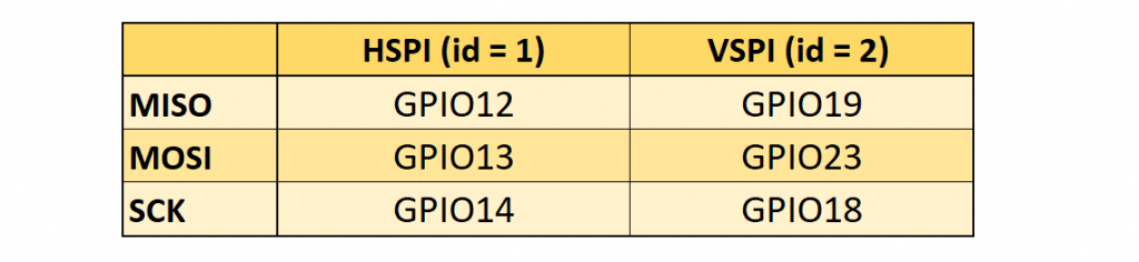 SPI Pins of the ESP32
You can easily change the pin assignment.
The creation of SPI objects is similar to I2C.
You can pass different parameters:
from machine import Pin, SPI
hspi = SPI(1) # use default Pins
hspi = SPI(1, 20000000)
hspi = SPI(1, baudrate=20000000, sck=Pin(14), mosi=Pin(13), miso=Pin(12))
vspi = SPI(2, baudrate=40000000, polarity=0, phase=0, bits=8, firstbit=0, sck=Pin(15), mosi=Pin(16), miso=Pin(17))
from machine import Pin, SPI
hspi = SPI(1) # use default Pins
hspi = SPI(1, 20000000)
hspi = SPI(1, baudrate=20000000, sck=Pin(14), mosi=Pin(13), miso=Pin(12))
vspi = SPI(2, baudrate=40000000, polarity=0, phase=0, bits=8, firstbit=0, sck=Pin(15), mosi=Pin(16), miso=Pin(17))
from machine import Pin, SPI
hspi = SPI(1) # use default Pins
hspi = SPI(1, 20000000)
hspi = SPI(1, baudrate=20000000, sck=Pin(14), mosi=Pin(13), miso=Pin(12))
vspi = SPI(2, baudrate=40000000, polarity=0, phase=0, bits=8, firstbit=0, sck=Pin(15), mosi=Pin(16), miso=Pin(17))
When using the standard GPIOs, the baud rate can be up to 80 MHz.
If you choose other GPIOs, the baud rate is limited to 40 MHz.
Reading and writing to registers is also similar.
The data is passed and received as bytearrays.
Here is an example of how to use the most important functions:
spi.read(5) # read 5 bytes
spi.read(5, 0xFF) # read 5 bytes and write 0xFF
buf = bytearray(20)
spi.readinto(buf) # read into the given buffer
spi.readinto(buf, 0xFF) # read into the buffer and write 0xFF
spi.write(buf) # write buffer
spi.write_readinto(buf_1, buf_2) # write buf_1 and read into the buf_2
SPI Pins of the ESP32
You can easily change the pin assignment.
The creation of SPI objects is similar to I2C.
You can pass different parameters:
from machine import Pin, SPI
hspi = SPI(1) # use default Pins
hspi = SPI(1, 20000000)
hspi = SPI(1, baudrate=20000000, sck=Pin(14), mosi=Pin(13), miso=Pin(12))
vspi = SPI(2, baudrate=40000000, polarity=0, phase=0, bits=8, firstbit=0, sck=Pin(15), mosi=Pin(16), miso=Pin(17))
from machine import Pin, SPI
hspi = SPI(1) # use default Pins
hspi = SPI(1, 20000000)
hspi = SPI(1, baudrate=20000000, sck=Pin(14), mosi=Pin(13), miso=Pin(12))
vspi = SPI(2, baudrate=40000000, polarity=0, phase=0, bits=8, firstbit=0, sck=Pin(15), mosi=Pin(16), miso=Pin(17))
from machine import Pin, SPI
hspi = SPI(1) # use default Pins
hspi = SPI(1, 20000000)
hspi = SPI(1, baudrate=20000000, sck=Pin(14), mosi=Pin(13), miso=Pin(12))
vspi = SPI(2, baudrate=40000000, polarity=0, phase=0, bits=8, firstbit=0, sck=Pin(15), mosi=Pin(16), miso=Pin(17))
When using the standard GPIOs, the baud rate can be up to 80 MHz.
If you choose other GPIOs, the baud rate is limited to 40 MHz.
Reading and writing to registers is also similar.
The data is passed and received as bytearrays.
Here is an example of how to use the most important functions:
spi.read(5) # read 5 bytes
spi.read(5, 0xFF) # read 5 bytes and write 0xFF
buf = bytearray(20)
spi.readinto(buf) # read into the given buffer
spi.readinto(buf, 0xFF) # read into the buffer and write 0xFF
spi.write(buf) # write buffer
spi.write_readinto(buf_1, buf_2) # write buf_1 and read into the buf_2
spi.read(5) # read 5 bytes
spi.read(5, 0xFF) # read 5 bytes and write 0xFF
buf = bytearray(20)
spi.readinto(buf) # read into the given buffer
spi.readinto(buf, 0xFF) # read into the buffer and write 0xFF
spi.write(buf) # write buffer
spi.write_readinto(buf_1, buf_2) # write buf_1 and read into the buf_2
spi.read(5) # read 5 bytes
spi.read(5, 0xFF) # read 5 bytes and write 0xFF
buf = bytearray(20)
spi.readinto(buf) # read into the given buffer
spi.readinto(buf, 0xFF) # read into the buffer and write 0xFF
spi.write(buf) # write buffer
spi.write_readinto(buf_1, buf_2) # write buf_1 and read into the buf_2
UART (Serial)
The ESP32 has the three UART interfaces UART0, UART1 and UART2.
By default, these are assigned to the following GPIOs:
 Standard GPIOs of the UART interfaces
When choosing the pins, you have to be a bit careful.
You should not use the standard GPIOS for UART0 and UART1 (see also here).
Things repeat.
Again, you first create a UART object, where you can pass several parameters.
At least you have to pass the UART ID.
Here is an example:
from machine import UART
uart1 = UART(1, baudrate=115200, tx=18, rx=19)
from machine import UART
uart1 = UART(1, baudrate=115200, tx=18, rx=19)
from machine import UART
uart1 = UART(1, baudrate=115200, tx=18, rx=19)
And here are a few – I think self-explanatory – statements:
uart1.init(9600, bits=8, parity=None, stop=1) # standard settings
uart1.read(7) # read 7 characters, returns a bytes object, not bytearray
uart1.read() # read all available characters
uart1.readline() # read a line
uart1.readinto(buf) # read and store into buf
uart1.write('xyz') # write the 3 characters
uart1.any() # returns number of bytes available
Standard GPIOs of the UART interfaces
When choosing the pins, you have to be a bit careful.
You should not use the standard GPIOS for UART0 and UART1 (see also here).
Things repeat.
Again, you first create a UART object, where you can pass several parameters.
At least you have to pass the UART ID.
Here is an example:
from machine import UART
uart1 = UART(1, baudrate=115200, tx=18, rx=19)
from machine import UART
uart1 = UART(1, baudrate=115200, tx=18, rx=19)
from machine import UART
uart1 = UART(1, baudrate=115200, tx=18, rx=19)
And here are a few – I think self-explanatory – statements:
uart1.init(9600, bits=8, parity=None, stop=1) # standard settings
uart1.read(7) # read 7 characters, returns a bytes object, not bytearray
uart1.read() # read all available characters
uart1.readline() # read a line
uart1.readinto(buf) # read and store into buf
uart1.write('xyz') # write the 3 characters
uart1.any() # returns number of bytes available
uart1.init(9600, bits=8, parity=None, stop=1) # standard settings
uart1.read(7) # read 7 characters, returns a bytes object, not bytearray
uart1.read() # read all available characters
uart1.readline() # read a line
uart1.readinto(buf) # read and store into buf
uart1.write('xyz') # write the 3 characters
uart1.any() # returns number of bytes available
uart1.init(9600, bits=8, parity=None, stop=1) # standard settings
uart1.read(7) # read 7 characters, returns a bytes object, not bytearray
uart1.read() # read all available characters
uart1.readline() # read a line
uart1.readinto(buf) # read and store into buf
uart1.write('xyz') # write the 3 characters
uart1.any() # returns number of bytes available
Deep and Light Sleep
To save power, the ESP32 has a light sleep and a deep sleep function.
After a light sleep, the program picks up where it left off.
A deep sleep causes a reset.
The setting is very easy on the ESP32 with MicroPython.
You can try the following program:
light_deep_sleep.py
import machine, time
if machine.reset_cause() == machine.DEEPSLEEP_RESET:
print("woke up from a deep sleep")
while True:
#machine.deepsleep(3000)
machine.lightsleep(3000)
print("woke up from a light sleep")
time.sleep(0.1)
import machine, time
if machine.reset_cause() == machine.DEEPSLEEP_RESET:
print("woke up from a deep sleep")
while True:
#machine.deepsleep(3000)
machine.lightsleep(3000)
print("woke up from a light sleep")
time.sleep(0.1)
import machine, time
if machine.reset_cause() == machine.DEEPSLEEP_RESET:
print("woke up from a deep sleep")
while True:
#machine.deepsleep(3000)
machine.lightsleep(3000)
print("woke up from a light sleep")
time.sleep(0.1)
Without the small time.sleep() delay, print() did not work properly for me.
Apparently, the ESP32 goes to sleep before the print() instruction is completely processed.
Touch Pins
The touch pins register capacities.
Since the human body also has a certain capacity, the touch pins serve as touch sensors.
Here’s how it works:
touch.py
from machine import TouchPad, Pin
from time import sleep
t = TouchPad(Pin(32))
while True:
t_val=t.read()
print("Touch value:", t_val)
sleep(0.5)
from machine import TouchPad, Pin
from time import sleep
t = TouchPad(Pin(32))
while True:
t_val=t.read()
print("Touch value:", t_val)
sleep(0.5)
from machine import TouchPad, Pin
from time import sleep
t = TouchPad(Pin(32))
while True:
t_val=t.read()
print("Touch value:", t_val)
sleep(0.5)
The initial values (ESP32 used on a breadboard) were around 800 for me.
When I touched the touch pin via a jumper cable, the values dropped below 100.
A touch event can wake the ESP32 from both light and deep sleep.
Here’s how it works:
import machine
from machine import TouchPad, Pin
import esp32
from time import sleep
t = TouchPad(Pin(32))
t.config(300) # configure the threshold at which the pin is considered touched
esp32.wake_on_touch(True)
while True:
machine.lightsleep() # put the MCU to sleep until a touchpad is touched
print("Woke up from light sleep")
sleep(1)
print("Falling asleep again")
sleep(0.1) # you can try without this
Hall Sensor
The ESP32 has a Hall sensor that detects magnetic fields.
It is easy to read:
import esp32, time
while True:
m = esp32.hall_sensor()
print(m)
time.sleep(2)
import esp32, time
while True:
m = esp32.hall_sensor()
print(m)
time.sleep(2)
import esp32, time
while True:
m = esp32.hall_sensor()
print(m)
time.sleep(2)
Wi-Fi
One of the great advantages of the ESP32 is the integrated WLAN.
However, the ESP32MicroPythontopic is quite extensive and would go beyond the scope of this post.
Maybe I’ll cover it in a later article.
If you want to deal with the ESP32MicroPythontopic in more detail, then I recommend this tutorial as a starting point.
There it is shown how to set up a web server with the ESP32 and how to then switch an LED via browser.
The instructions worked wonderfully for me right away.
Bluetooth
With Bluetooth, a distinction is made – among many other things – between Bluetooth Classic and BLE (Bluetooth Low Energy).
You may know the classic version from the HC-05 and HC-06 modules or from my article about programming the ESP32 with Arduino code. The advantage is the simple programming.
The BLE variant, as its name suggests, is more energy-saving.
More about the differences between Classic and BLE can be found here.
Unfortunately, Classic Bluetooth is not (yet?) implemented in MicroPython.
On the other hand, BLE is a somewhat more complex ESP32MicroPythontopic that would go beyond the scope here.
And honestly, I have some learning to do on this ESP32MicroPythontopic as well.
Getting started with MicroPython on the ESP32
Using MicroPython is a great way to get the most of your ESP32 board.
And vice versa, the ESP32 chip is a great platform for using MicroPython.
This tutorial will guide you through setting up MicroPython, getting a prompt, using WebREPL, connecting to the network and communicating with the Internet, using the hardware peripherals, and controlling some external components.
Let’s get started!
1.1. Requirements
The first thing you need is a board with an ESP32 chip.
The MicroPython software supports the ESP32 chip itself and any board should work.
The main characteristic of a board is how the GPIO pins are connected to the outside world, and whether it includes a built-in USB-serial converter to make the UART available to your PC.
Names of pins will be given in this tutorial using the chip names (eg GPIO2) and it should be straightforward to find which pin this corresponds to on your particular board.
1.2. Powering the board
If your board has a USB connector on it then most likely it is powered through this when connected to your PC.
Otherwise you will need to power it directly.
Please refer to the documentation for your board for further details.
1.3. Getting the firmware
The first thing you need to do is download the most recent MicroPython firmware .bin file to load onto your ESP32 device. You can download it from the
MicroPython downloads page.
From here, you have 3 main choices:
Stable firmware builds
Daily firmware builds
Daily firmware builds with SPIRAM support
If you are just starting with MicroPython, the best bet is to go for the Stable firmware builds. If you are an advanced, experienced MicroPython ESP32 user who would like to follow development closely and help with testing new features, there are daily builds.
If your board has SPIRAM support you can use either the standard firmware or the firmware with SPIRAM support, and in the latter case you will have access to more RAM for Python objects.
1.4. Deploying the firmware
Once you have the MicroPython firmware you need to load it onto your ESP32 device.
There are two main steps to do this: first you need to put your device in bootloader mode, and second you need to copy across the firmware.
The exact procedure for these steps is highly dependent on the particular board and you will need to refer to its documentation for details.
Fortunately, most boards have a USB connector, a USB-serial converter, and the DTR and RTS pins wired in a special way then deploying the firmware should be easy as all steps can be done automatically.
Boards that have such features include the Adafruit Feather HUZZAH32, M5Stack, Wemos LOLIN32, and TinyPICO boards, along with the Espressif DevKitC, PICO-KIT, WROVER-KIT dev-kits.
For best results it is recommended to first erase the entire flash of your device before putting on new MicroPython firmware.
Currently we only support esptool.py to copy across the firmware.
You can find this tool here: https://github.com/espressif/esptool/, or install it using pip:
pip install esptool
Versions starting with 1.3 support both Python 2.7 and Python 3.4 (or newer).
An older version (at least 1.2.1 is needed) works fine but will require Python 2.7.
Using esptool.py you can erase the flash with the command:
esptool.py --port /dev/ttyUSB0 erase_flash
And then deploy the new firmware using:
esptool.py --chip esp32 --port /dev/ttyUSB0 write_flash -z 0x1000 esp32-20180511-v1.9.4.bin
Notes:
You might need to change the “port” setting to something else relevant for your PC
You may need to reduce the baudrate if you get errors when flashing (eg down to 115200 by adding --baud 115200 into the command)
For some boards with a particular FlashROM configuration you may need to change the flash mode (eg by adding -fm dio into the command)
The filename of the firmware should match the file that you have
If the above commands run without error then MicroPython should be installed on your board!
1.5. Serial prompt
Once you have the firmware on the device you can access the REPL (Python prompt) over UART0 (GPIO1=TX, GPIO3=RX), which might be connected to a USB-serial converter, depending on your board.
The baudrate is 115200.
From here you can now follow the ESP8266 tutorial, because these two Espressif chips are very similar when it comes to using MicroPython on them.
The ESP8266 tutorial is found at MicroPython tutorial for ESP8266 (but skip the Introduction section).
1.6. Troubleshooting installation problems
If you experience problems during flashing or with running firmware immediately after it, here are troubleshooting recommendations:
Be aware of and try to exclude hardware problems.
There are 2 common problems: bad power source quality, and worn-out/defective FlashROM.
Speaking of power source, not just raw amperage is important, but also low ripple and noise/EMI in general.
The most reliable and convenient power source is a USB port.
The flashing instructions above use flashing speed of 460800 baud, which is good compromise between speed and stability. However, depending on your module/board, USB-UART converter, cables, host OS, etc., the above baud rate may be too high and lead to errors. Try a more common 115200 baud rate instead in such cases.
To catch incorrect flash content (e.g. from a defective sector on a chip), add --verify switch to the commands above.
If you still experience problems with flashing the firmware please refer to esptool.py project page, https://github.com/espressif/esptool for additional documentation and a bug tracker where you can report problems.
If you are able to flash the firmware but the --verify option returns errors even after multiple retries the you may have a defective FlashROM chip.
ESP32/ESP8266 MicroPython Web Server
We’ll build a web server with ON and OFF buttons to control the on-board LED of the ESP32/ESP8266.
We’ll use sockets and the Python socket API.

Prerequisites
To program the ESP32 and ESP8266 with MicroPython, we use uPyCraft IDE as a programming environment.
Follow the next tutorials to install uPyCraft IDE and flash MicroPython firmware on your board:
Install uPyCraft IDE: Windows PC,
MacOS X, or
Linux Ubuntu
Flash/Upload MicroPython Firmware to ESP32 and ESP8266
If this is your first time dealing with MicroPython you may find these next tutorials useful:
Getting Started with MicroPython on ESP32 and ESP8266
MicroPython Programming Basics with ESP32 and ESP8266
MicroPython with ESP32 and ESP8266: Interacting with GPIOs
-Parts required
For this tutorial you need an ESP32 or ESP8266 board:
ESP32 DEVKIT DOIT board – read ESP32 Development Boards Review and Comparison
ESP8266-12E NodeMCU Kit – read Best ESP8266 Wi-Fi Development Board
You can use the preceding links or go directly to MakerAdvisor.com/tools to find all the parts for your projects at the best price!
Preparing the Files
Connect the ESP32 or ESP8266 board to your computer.
Open uPyCraft IDE, and go to Tools > Serial and select the serial port.
 You should see the files on the ESP32/ESP8266 board on the device folder.
By default, when you burn MicroPython firmware, a boot.py file is created.
For this project you’ll need a boot.py file and a main.py file.
The boot.py file has the code that only needs to run once on boot.
This includes importing libraries, network credentials, instantiating pins, connecting to your network, and other configurations.
The main.py file will contain the code that runs the web server to serve files and perform tasks based on the requests received by the client.
You should see the files on the ESP32/ESP8266 board on the device folder.
By default, when you burn MicroPython firmware, a boot.py file is created.
For this project you’ll need a boot.py file and a main.py file.
The boot.py file has the code that only needs to run once on boot.
This includes importing libraries, network credentials, instantiating pins, connecting to your network, and other configurations.
The main.py file will contain the code that runs the web server to serve files and perform tasks based on the requests received by the client.
-Creating the main.py file on your board
Press the “New file” button to create a new file.
Press the “Save file” button to save the file in your computer.
 A new window opens, name your file main.py and save it in your computer:
 After that, you should see the following in your uPyCraft IDE (the boot.py file in your device and a new tab with the main.py file):
 Click the “Download and run” button to upload the file to your ESP board:
 The device directory should now load the main.py file.
Your ESP has the file main.py stored.
The device directory should now load the main.py file.
Your ESP has the file main.py stored.

-boot.py
Copy the following code to the ESP32/ESP8266 boot.py file.
# Complete project details at https://RandomNerdTutorials.com
try:
import usocket as socket
except:
import socket
from machine import Pin
import network
import esp
esp.osdebug(None)
import gc
gc.collect()
ssid = 'REPLACE_WITH_YOUR_SSID'
password = 'REPLACE_WITH_YOUR_PASSWORD'
station = network.WLAN(network.STA_IF)
station.active(True)
station.connect(ssid, password)
while station.isconnected() == False:
pass
print('Connection successful')
print(station.ifconfig())
led = Pin(2, Pin.OUT)
View raw code
As mentioned previously, we create our web server using sockets and the Python socket API.
The official documentation imports the socket library as follows:
try:
import usocket as socket
except:
import socket
We need to import the Pin class from the machine module to be able to interact with the GPIOs.
from machine import Pin
After importing the socket library, we need to import the network library.
The network library allows us to connect the ESP32 or ESP8266 to a Wi-Fi network.
import network
The following lines turn off vendor OS debugging messages:
import esp
esp.osdebug(None)
Then, we run a garbage collector:
import gc
gc.collect()
A garbage collector is a form of automatic memory management.
This is a way to reclaim memory occupied by objects that are no longer in used by the program.
This is useful to save space in the flash memory.
The following variables hold your network credentials:
ssid = 'REPLACE_WITH_YOUR_SSID'
password = 'replace_with_your_password'
You should replace the words highlighted in red with your network SSID and password, so that the ESP is able to connect to your router.
Then, set the ESP32 or ESP8266 as a Wi-Fi station:
station = network.WLAN(network.STA_IF)
After that, activate the station:
station.active(True)
Finally, the ESP32/ESP8266 connects to your router using the SSID and password defined earlier:
station.connect(ssid, password)
The following statement ensures that the code doesn’t proceed while the ESP is not connected to your network.
while station.isconnected() == False:
pass
After a successful connection, print network interface parameters like the ESP32/ESP8266 IP address – use the ifconfig() method on the station object.
print('Connection successful')
print(station.ifconfig())
Create a Pin object called led that is an output, that refers to the ESP32/ESP8266 GPIO2:
led = Pin(2, Pin.OUT)
-main.py
Copy the following code to the ESP32/ESP8266 main.py file.
# Complete project details at https://RandomNerdTutorials.com
def web_page():
if led.value() == 1:
gpio_state="ON"
else:
gpio_state="OFF"
html = """<html><head> <title>ESP Web Server</title> <meta name="viewport" content="width=device-width, initial-scale=1">
<link rel="icon" href="data:,"> <style>html{font-family: Helvetica; display:inline-block; margin: 0px auto; text-align: center;}
h1{color: #0F3376; padding: 2vh;}p{font-size: 1.5rem;}.button{display: inline-block; background-color: #e7bd3b; border: none;
border-radius: 4px; color: white; padding: 16px 40px; text-decoration: none; font-size: 30px; margin: 2px; cursor: pointer;}
.button2{background-color: #4286f4;}</style></head><body> <h2>ESP Web Server</h2>
<p>GPIO state: <strong>""" + gpio_state + """</strong></p><p><a href="/?led=on"><button class="button">ON</button></a></p>
<p><a href="/?led=off"><button class="button button2">OFF</button></a></p></body></html>"""
return html
s = socket.socket(socket.AF_INET, socket.SOCK_STREAM)
s.bind(('', 80))
s.listen(5)
while True:
conn, addr = s.accept()
print('Got a connection from %s' % str(addr))
request = conn.recv(1024)
request = str(request)
print('Content = %s' % request)
led_on = request.find('/?led=on')
led_off = request.find('/?led=off')
if led_on == 6:
print('LED ON')
led.value(1)
if led_off == 6:
print('LED OFF')
led.value(0)
response = web_page()
conn.send('HTTP/1.1 200 OK\n')
conn.send('Content-Type: text/html\n')
conn.send('Connection: close\n\n')
conn.sendall(response)
conn.close()
View raw code
The script starts by creating a function called web_page().
This function returns a variable called html that contains the HTML text to build the web page.
def web_page():
The web page displays the current GPIO state.
So, before generating the HTML text, we need to check the LED state.
We save its state on the gpio_state variable:
if led.value() == 1:
gpio_state="ON"
else:
gpio_state="OFF"
After that, the gpio_state variable is incorporated into the HTML text using “+” signs to concatenate strings.
html = """<html><head> <title>ESP Web Server</title> <meta name="viewport" content="width=device-width, initial-scale=1">
<link rel="icon" href="data:,"> <style>html{font-family: Helvetica; display:inline-block; margin: 0px auto; text-align: center;}
h1{color: #0F3376; padding: 2vh;}p{font-size: 1.5rem;}.button{display: inline-block; background-color: #e7bd3b; border: none;
border-radius: 4px; color: white; padding: 16px 40px; text-decoration: none; font-size: 30px; margin: 2px; cursor: pointer;}
.button2{background-color: #4286f4;}</style></head><body> <h2>ESP Web Server</h2>
<p>GPIO state: <strong>""" + gpio_state + """</strong></p><p><a href="/?led=on"><button >ON</button></a></p>
<p><a href="/?led=off"><button >OFF</button></a></p></body></html>"""
-Creating a socket server
After creating the HTML to build the web page, we need to create a listening socket to listen for incoming requests and send the HTML text in response.
For a better understanding, the following figure shows a diagram on how to create sockets for server-client interaction:
 Create a socket using socket.socket(), and specify the socket type.
We create a new socket object called s with the given address family, and socket type.
This is a STREAM TCP socket:
s = socket.socket(socket.AF_INET, socket.SOCK_STREAM)
Next, bind the socket to an address (network interface and port number) using the bind() method.
The bind() method accepts a tupple variable with the ip address, and port number:
s.bind(('', 80))
In our example, we are passing an empty string ‘ ‘ as an IP address and port 80.
In this case, the empty string refers to the localhost IP address (this means the ESP32 or ESP8266 IP address).
The next line enables the server to accept connections; it makes a “listening” socket.
The argument specifies the maximum number of queued connections.
The maximum is 5.
s.listen(5)
In the while loop is where we listen for requests and send responses.
When a client connects, the server calls the accept() method to accept the connection.
When a client connects, it saves a new socket object to accept and send data on the conn variable, and saves the client address to connect to the server on the addr variable.
conn, addr = s.accept()
Then, print the address of the client saved on the addr variable.
print('Got a connection from %s' % str(addr))
The data is exchanged between the client and server using the send() and recv() methods.
The following line gets the request received on the newly created socket and saves it in the request variable.
request = conn.recv(1024)
The recv() method receives the data from the client socket (remember that we’ve created a new socket object on the conn variable).
The argument of the recv() method specifies the maximum data that can be received at once.
The next line simply prints the content of the request:
print('Content = %s' % str(request))
Then, create a variable called response that contains the HTML text returned by the web_page() function:
response = web_page()
Finally, send the response to the socket client using the send() and sendall() methods:
conn.send('HTTP/1.1 200 OK\n')
conn.send('Content-Type: text/html\n')
conn.send('Connection: close\n\n')
conn.sendall(response)
In the end, close the created socket.
conn.close()
Create a socket using socket.socket(), and specify the socket type.
We create a new socket object called s with the given address family, and socket type.
This is a STREAM TCP socket:
s = socket.socket(socket.AF_INET, socket.SOCK_STREAM)
Next, bind the socket to an address (network interface and port number) using the bind() method.
The bind() method accepts a tupple variable with the ip address, and port number:
s.bind(('', 80))
In our example, we are passing an empty string ‘ ‘ as an IP address and port 80.
In this case, the empty string refers to the localhost IP address (this means the ESP32 or ESP8266 IP address).
The next line enables the server to accept connections; it makes a “listening” socket.
The argument specifies the maximum number of queued connections.
The maximum is 5.
s.listen(5)
In the while loop is where we listen for requests and send responses.
When a client connects, the server calls the accept() method to accept the connection.
When a client connects, it saves a new socket object to accept and send data on the conn variable, and saves the client address to connect to the server on the addr variable.
conn, addr = s.accept()
Then, print the address of the client saved on the addr variable.
print('Got a connection from %s' % str(addr))
The data is exchanged between the client and server using the send() and recv() methods.
The following line gets the request received on the newly created socket and saves it in the request variable.
request = conn.recv(1024)
The recv() method receives the data from the client socket (remember that we’ve created a new socket object on the conn variable).
The argument of the recv() method specifies the maximum data that can be received at once.
The next line simply prints the content of the request:
print('Content = %s' % str(request))
Then, create a variable called response that contains the HTML text returned by the web_page() function:
response = web_page()
Finally, send the response to the socket client using the send() and sendall() methods:
conn.send('HTTP/1.1 200 OK\n')
conn.send('Content-Type: text/html\n')
conn.send('Connection: close\n\n')
conn.sendall(response)
In the end, close the created socket.
conn.close()
Testing the Web Server
Upload the main.py and boot.py files to the ESP32/ESP8266.
Your device folder should contain two files: boot.py and main.py.
After uploading the files, press the ESP EN/RST on-board button.
 After a few seconds, it should establish a connection with your router and print the IP address on the Shell.
 Open your browser, and type your ESP IP address you’ve just found.
You should see the web server page as shown below.
Open your browser, and type your ESP IP address you’ve just found.
You should see the web server page as shown below.
 When you press the ON button, you make a request on the ESP IP address followed by /?led=on.
The ESP32/ESP8266 on-board LED turns on, and the GPIO state is updated on the page.
Note: some ESP8266 on-board LEDs turn on the LED with an OFF command, and turn off the LED with the ON command.
When you press the ON button, you make a request on the ESP IP address followed by /?led=on.
The ESP32/ESP8266 on-board LED turns on, and the GPIO state is updated on the page.
Note: some ESP8266 on-board LEDs turn on the LED with an OFF command, and turn off the LED with the ON command.
 When you press the OFF button, you make a request on the ESP IP address followed by /?led=off.
The LED turns off, and the GPIO state is updated.
When you press the OFF button, you make a request on the ESP IP address followed by /?led=off.
The LED turns off, and the GPIO state is updated.
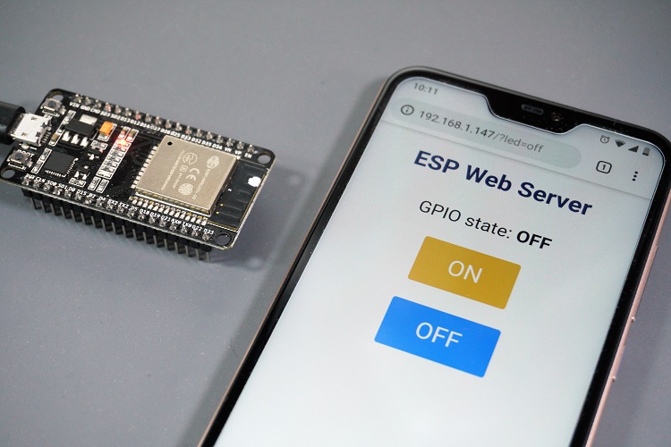 Note: to keep this tutorial simple, we’re controlling the on-board LED that corresponds to GPIO 2.
You can control any other GPIO with any other output (a relay, for example) using the same method.
Also, you can modify the code to control multiple GPIOs or change the HTML text to create a different web page.
Note: to keep this tutorial simple, we’re controlling the on-board LED that corresponds to GPIO 2.
You can control any other GPIO with any other output (a relay, for example) using the same method.
Also, you can modify the code to control multiple GPIOs or change the HTML text to create a different web page.
Wrapping Up
This tutorial showed you how to build a simple web server with MicroPython firmware to control the ESP32/ESP8266 GPIOs using sockets and the Python socket library.
If you’re looking for a web server tutorial with Arduino IDE, you can check the following resources:
ESP32 Web Server – Arduino IDE
ESP8266 Web Server – Arduino IDE
MicroPython Web Server Guide W Examples
In this guide, learn how to control GPIOs and read sensor data remotely using a MicroPython web server.
Examples are discussed using Raspberry Pi Pico W and ESP32 development boards.
The web server code discussed here is robust and can automatically make reconnection attempts in case of connection failure.
The code can be easily adapted for other development boards such as the ESP8266.
Your microcontroller has to be connected to the same network as your computer or mobile phone to access the web server from a browser.
Connecting to the web server from anywhere via the internet is out of the scope of this article.
Brief Overview of a Web Server
In the context of embedded systems and IoT, a web server is a specialized software application running on a microcontroller or microprocessor that enables the device to respond to HTTP (Hypertext Transfer Protocol) requests.
HTTP is a protocol used for transmitting data on the World Wide Web.
![]() So, a web server running on a microcontroller helps to communicate and exchange information with other devices, typically through a web browser.
This can be used for remote monitoring and control.
For example, you might access the settings of a smart thermostat or a network-connected sensor through a web browser.
Behind the scenes, a web server will handle the communication and serve the requested web pages.
So, a web server running on a microcontroller helps to communicate and exchange information with other devices, typically through a web browser.
This can be used for remote monitoring and control.
For example, you might access the settings of a smart thermostat or a network-connected sensor through a web browser.
Behind the scenes, a web server will handle the communication and serve the requested web pages.
Prerequisites
The following components will be used in this guide:
Raspberry Pi Pico W development board.
ESP32 development board.
ESP-WROOM-32 is used here, but you can select any alternative.
LEDs and current limiting resistors.
You will also have to flash MicroPython firmware on your development board.
If you are using ESP32, read these guides:
Getting Started: MicroPython On ESP32 Using uPyCraft IDE.
How-To: MicroPython On ESP32 Using Thonny IDE (Flash/Upload).
To flash and run MicroPython firmware on Raspberry Pi Pico / Pico W, read:
Getting Started – Raspberry Pi Pico & Pico W with MicroPython
MicroPython Web Server Example 1: Control GPIOs in ESP32
This web server example will display a graphical user interface (GUI) in a browser which will give control of the GPIOs of ESP32.
The schematic below shows how to connect two LEDs to the GPIOs of ESP32.
I have used an ESP-WROOM-32 board in this tutorial, but any other ESP32 board will also work.
Connect two LEDs to ESP32 as shown:
![]() Make sure to use proper current limiting resistors with the LEDs.
Make sure to use proper current limiting resistors with the LEDs.
-Uploading Code – ESP32 MicroPython Web Server
After the connections are done and the MicroPython .bin file has been uploaded to ESP32, you can proceed with uploading the code to ESP32.
The code will run a web server in ESP32 and listen for HTTP requests from clients.
The steps below explain how to upload web server MicroPython code to ESP32 using Thonny IDE.
In Thonny IDE, set the interpreter to ESP32 by navigating to Tools>Options>Interpreter.
![]() Create a new file by clicking on File>New and paste the following MicroPython code for the web server.
from machine import Pin
import network
import socket
import time
# Define GPIO pins
GPIO1 = Pin(22, Pin.OUT)
GPIO2 = Pin(23, Pin.OUT)
# Initialize GPIO states
GPIO1.value(0) # OFF
GPIO2.value(0) # OFF
GPIO1_state = "GPIO 1 is OFF"
GPIO2_state = "GPIO 2 is OFF"
#WiFi credentials
ssid = 'YOUR_SSID'
password = 'YOUR_PASSWORD'
wlan = network.WLAN(network.STA_IF)
#function to connect to Wi-Fi network
def cnctWifi():
wlan.active(True)
print('Attempting to connect to the network...')
wlan.connect(ssid, password)
max_wait = 10
while max_wait > 0:
if wlan.isconnected():
break
max_wait -= 1
print('waiting for connection...')
time.sleep(1)
# Manage connection errors
if not wlan.isconnected():
print('Network Connection has failed')
else:
print('Connected to the network successfully.')
status = wlan.ifconfig()
print( 'Enter this address in browser = ' + status[0] )
#HTML + CSS for webpage
html = """<!DOCTYPE html>
<html lang="en">
<head>
<meta charset="UTF-8">
<meta name="viewport" content="width=device-width, initial-scale=1">
<title>MicroPython Web Server</title>
<style>
html {
font-family: Arial;
display: inline-block;
margin: 0px auto;
text-align: center;
}
h1 {
font-family: Arial;
color: #2551cc;
}
.button1,
.button2 {
-webkit-border-radius: 10;
-moz-border-radius: 10;
border-radius: 10px;
font-family: Arial;
color: #ffffff;
font-size: 30px;
padding: 10px 20px 10px 20px;
text-decoration: none;
display: inline-block;
margin: 5px;
}
.button1 {
background: #339966;
}
.button2 {
background: #993300;
}
</style>
</head>
<body>
<h1>MicroPython Web Server</h1>
<p>%s</p>
<p>
<a href="/GPIO1/on"><button >GPIO 1 ON</button></a>
<a href="/GPIO1/off"><button >GPIO 1 OFF</button></a>
</p>
<p>%s</p>
<p>
<a href="/GPIO2/on"><button >GPIO 2 ON</button></a>
<a href="/GPIO2/off"><button >GPIO 2 OFF</button></a>
</p>
</body>
</html>
"""
# Connect to Wi-Fi
cnctWifi()
# Set up socket for web server
addr = socket.getaddrinfo('0.0.0.0', 80)[0][-1]
s = socket.socket()
s.setblocking(0)
s.bind(addr)
s.listen(1)
print('listening on', addr)
# Main loop for handling client requests
while True:
if not wlan.isconnected():
print("Connection failed.
Trying to reconnect")
wlan.disconnect()
cnctWifi()
try:
cl, addr = s.accept()
print('client connected from', addr)
request = cl.recv(1024)
print(request)
request = str(request)
GPIO1_on = request.find('/GPIO1/on')
GPIO1_off = request.find('/GPIO1/off')
GPIO2_on = request.find('/GPIO2/on')
GPIO2_off = request.find('/GPIO2/off')
if GPIO1_on == 6:
print("GPIO 1 is on")
GPIO1.value(1)
GPIO1_state = "GPIO 1 is ON"
if GPIO1_off == 6:
print("GPIO 1 is off")
GPIO1.value(0)
GPIO1_state = "GPIO 1 is OFF"
if GPIO2_on == 6:
print("GPIO 2 is on")
GPIO2.value(1)
GPIO2_state = "GPIO 2 is ON"
if GPIO2_off == 6:
print("GPIO 2 is off")
GPIO2.value(0)
GPIO2_state = "GPIO 2 is OFF"
response = html % (GPIO1_state, GPIO2_state)
cl.send('HTTP/1.0 200 OK\r\nContent-type: text/html\r\n\r\n')
cl.send(response)
cl.close()
except:
pass
time.sleep(0.1)Code language: Python (python)
The code is explained shortly below.
You will have to change the Wi-Fi credentials to your own in the code by replacing YOUR_SSID and YOUR_PASSWORD.
ssid = 'YOUR_SSID'
password = 'YOUR_PASSWORD'Code language: JavaScript (javascript)
Save the file by clicking on File>Save as or by using the shortcut Ctrl+Shift+S.
Select MicroPython Device on the window that appears to save the code to ESP32.
Create a new file by clicking on File>New and paste the following MicroPython code for the web server.
from machine import Pin
import network
import socket
import time
# Define GPIO pins
GPIO1 = Pin(22, Pin.OUT)
GPIO2 = Pin(23, Pin.OUT)
# Initialize GPIO states
GPIO1.value(0) # OFF
GPIO2.value(0) # OFF
GPIO1_state = "GPIO 1 is OFF"
GPIO2_state = "GPIO 2 is OFF"
#WiFi credentials
ssid = 'YOUR_SSID'
password = 'YOUR_PASSWORD'
wlan = network.WLAN(network.STA_IF)
#function to connect to Wi-Fi network
def cnctWifi():
wlan.active(True)
print('Attempting to connect to the network...')
wlan.connect(ssid, password)
max_wait = 10
while max_wait > 0:
if wlan.isconnected():
break
max_wait -= 1
print('waiting for connection...')
time.sleep(1)
# Manage connection errors
if not wlan.isconnected():
print('Network Connection has failed')
else:
print('Connected to the network successfully.')
status = wlan.ifconfig()
print( 'Enter this address in browser = ' + status[0] )
#HTML + CSS for webpage
html = """<!DOCTYPE html>
<html lang="en">
<head>
<meta charset="UTF-8">
<meta name="viewport" content="width=device-width, initial-scale=1">
<title>MicroPython Web Server</title>
<style>
html {
font-family: Arial;
display: inline-block;
margin: 0px auto;
text-align: center;
}
h1 {
font-family: Arial;
color: #2551cc;
}
.button1,
.button2 {
-webkit-border-radius: 10;
-moz-border-radius: 10;
border-radius: 10px;
font-family: Arial;
color: #ffffff;
font-size: 30px;
padding: 10px 20px 10px 20px;
text-decoration: none;
display: inline-block;
margin: 5px;
}
.button1 {
background: #339966;
}
.button2 {
background: #993300;
}
</style>
</head>
<body>
<h1>MicroPython Web Server</h1>
<p>%s</p>
<p>
<a href="/GPIO1/on"><button >GPIO 1 ON</button></a>
<a href="/GPIO1/off"><button >GPIO 1 OFF</button></a>
</p>
<p>%s</p>
<p>
<a href="/GPIO2/on"><button >GPIO 2 ON</button></a>
<a href="/GPIO2/off"><button >GPIO 2 OFF</button></a>
</p>
</body>
</html>
"""
# Connect to Wi-Fi
cnctWifi()
# Set up socket for web server
addr = socket.getaddrinfo('0.0.0.0', 80)[0][-1]
s = socket.socket()
s.setblocking(0)
s.bind(addr)
s.listen(1)
print('listening on', addr)
# Main loop for handling client requests
while True:
if not wlan.isconnected():
print("Connection failed.
Trying to reconnect")
wlan.disconnect()
cnctWifi()
try:
cl, addr = s.accept()
print('client connected from', addr)
request = cl.recv(1024)
print(request)
request = str(request)
GPIO1_on = request.find('/GPIO1/on')
GPIO1_off = request.find('/GPIO1/off')
GPIO2_on = request.find('/GPIO2/on')
GPIO2_off = request.find('/GPIO2/off')
if GPIO1_on == 6:
print("GPIO 1 is on")
GPIO1.value(1)
GPIO1_state = "GPIO 1 is ON"
if GPIO1_off == 6:
print("GPIO 1 is off")
GPIO1.value(0)
GPIO1_state = "GPIO 1 is OFF"
if GPIO2_on == 6:
print("GPIO 2 is on")
GPIO2.value(1)
GPIO2_state = "GPIO 2 is ON"
if GPIO2_off == 6:
print("GPIO 2 is off")
GPIO2.value(0)
GPIO2_state = "GPIO 2 is OFF"
response = html % (GPIO1_state, GPIO2_state)
cl.send('HTTP/1.0 200 OK\r\nContent-type: text/html\r\n\r\n')
cl.send(response)
cl.close()
except:
pass
time.sleep(0.1)Code language: Python (python)
The code is explained shortly below.
You will have to change the Wi-Fi credentials to your own in the code by replacing YOUR_SSID and YOUR_PASSWORD.
ssid = 'YOUR_SSID'
password = 'YOUR_PASSWORD'Code language: JavaScript (javascript)
Save the file by clicking on File>Save as or by using the shortcut Ctrl+Shift+S.
Select MicroPython Device on the window that appears to save the code to ESP32.
![]() Set the filename as webserver.py in the next dialog box.
You can save it as main.py if you wish your code to run automatically when ESP32 boots.
Set the filename as webserver.py in the next dialog box.
You can save it as main.py if you wish your code to run automatically when ESP32 boots.
-Control GPIOs from any Browser
In Thonny IDE, click the shortcut F5 or the Run button to run the web server script that you saved to ESP32.
![]() If you face an error while running the script, refer to the troubleshooting section below.
Thereafter you must see some information in the shell of Thonny IDE.
The output messages will help you to know if a proper connection is established.
If you face an error while running the script, refer to the troubleshooting section below.
Thereafter you must see some information in the shell of Thonny IDE.
The output messages will help you to know if a proper connection is established.
![]() When a connection is successfully established, you will be presented with an IP address.
This IP address has to be entered in a browser connected to the same network.
When you enter the IP address in a browser, you should see the webpage as shown below.
When a connection is successfully established, you will be presented with an IP address.
This IP address has to be entered in a browser connected to the same network.
When you enter the IP address in a browser, you should see the webpage as shown below.
![]() When we click a button on the webpage, an HTTP request will be made.
For example, if we click the button to switch on GPIO1, the request will be like – 192.168.xx.xx//GPIO1/on.
This can be seen below in the screenshot taken after clicking on the button ‘GPIO 1 ON’.
When we click a button on the webpage, an HTTP request will be made.
For example, if we click the button to switch on GPIO1, the request will be like – 192.168.xx.xx//GPIO1/on.
This can be seen below in the screenshot taken after clicking on the button ‘GPIO 1 ON’.
![]() Similarly, each button click will send a unique request, and in response, the status of the toggled GPIO will also be displayed on the webpage.
Similarly, each button click will send a unique request, and in response, the status of the toggled GPIO will also be displayed on the webpage.
-MicroPython Code Explanation
Firstly, import the necessary libraries/modules The Pin class from the machine module is used to interact with GPIO.
The network module provides functionality related to network connections via Wi-Fi.
The socket module is used for working with sockets, which facilitate the sending and receiving of data over a network.
The time module is used for introducing delays in the code.
from machine import Pin
import network
import socket
import timeCode language: JavaScript (javascript)
We then initialize two GPIO pins GPIO1 and GPIO2 with ESP32 PINs 22 and 23, respectively.
Both pins are configured for output (Pin.OUT).
The initial state of both pins is set to “OFF” (logic level 0), and corresponding state variables (GPIO1_state and GPIO2_state) are defined with their initial states as strings.
# Define GPIO pins
GPIO1 = Pin(22, Pin.OUT)
GPIO2 = Pin(23, Pin.OUT)
# Initialize GPIO states
GPIO1.value(0) # OFF
GPIO2.value(0) # OFF
GPIO1_state = "GPIO 1 is OFF"
GPIO2_state = "GPIO 2 is OFF"Code language: PHP (php)
You should replace YOUR_SSID with the actual name of your Wi-Fi network and YOUR_PASSWORD with the actual password for that network.
These credentials are necessary for the device to successfully connect to the Wi-Fi network.
ssid = 'YOUR_SSID'
password = 'YOUR_PASSWORD'Code language: JavaScript (javascript)
The next line of code creates a WLAN interface in Station mode (STA_IF) and assigning it to the variable wlan
wlan = network.WLAN(network.STA_IF)
There are two Wi-Fi interfaces available: one for the station and one for the access point.
In station mode, Raspberry Pi Pico can connect to a Wi-Fi router.
In the Access Point mode, Raspberry Pi Pico can act as a WiFi hotspot.
You can learn more about it:
Raspberry Pi Pico W Wi-Fi Guide – Internet Access Example.
![]()
Connecting to Wi-Fi
Next, define a function cnctWifi() to make robust connections to the Wi-Fi network.
The function can make multiple attempts to connect and print an IP address which can be used to access the web server.
def cnctWifi():
wlan.active(True)
print('Attempting to connect to the network...')
wlan.connect(ssid, password)
max_wait = 10
while max_wait > 0:
if wlan.isconnected():
break
max_wait -= 1
print('waiting for connection...')
time.sleep(1)
# Manage connection errors
if not wlan.isconnected():
print('Network Connection has failed')
else:
print('Connected to the network successfully.')
status = wlan.ifconfig()
print( 'Enter this address in browser = ' + status[0] )Code language: Python (python)
Thereafter, define a multiline string (html) containing both HTML and CSS code to create a simple web page.
The code contains the HTML structure, CSS styling, Buttons with hyperlinks, and placeholders for dynamic content.
The %s within code acts as a placeholder for dynamic content that will be inserted at those positions.
The dynamic content here is the status of the GPIOs that will be changed.
Socket Setup
![]() Image credit: IBM
A socket is one endpoint of two-way communication.
We set up a basic server socket with the following lines of code.
addr = socket.getaddrinfo('0.0.0.0', 80)[0][-1]
s = socket.socket()
s.setblocking(0)
s.bind(addr)
s.listen(1)Code language: JavaScript (javascript)
Here is a brief explanation:
Image credit: IBM
A socket is one endpoint of two-way communication.
We set up a basic server socket with the following lines of code.
addr = socket.getaddrinfo('0.0.0.0', 80)[0][-1]
s = socket.socket()
s.setblocking(0)
s.bind(addr)
s.listen(1)Code language: JavaScript (javascript)
Here is a brief explanation:
addr = socket.getaddrinfo('0.0.0.0', 80)[0][-1]:
Retrieves address information for ‘0.0.0.0’ (which typically means listen on all available interfaces) on port 80 and stores it in the addr variable.
s = socket.socket():
Creates a new socket and assigns it to the variable s.
s.setblocking(0):
Sets the socket to non-blocking mode, meaning it won’t block the program’s execution while waiting for operations.
s.bind(addr):
Binds the socket to the address specified in the addr variable (in this case, ‘0.0.0.0’ on port 80).
s.listen(1):
Configures the socket to listen for incoming connections with a backlog of 1, allowing the server to accept one connection at a time.
An infinite while loop maintains a connection to Wi-Fi and does client request handling.
Each time the loop runs, it first checks if the Wi-Fi connection is active.
If not, it makes attempts to reconnect.
if not wlan.isconnected():
print("Connection failed.
Trying to reconnect")
wlan.disconnect()
cnctWifi()Code language: Python (python)
In a try block, the code handles incoming client requests, interprets them to control GPIO pins, and sends back an HTTP response.
Let’s break down the key parts:
Accept a Client Connection
cl, addr = s.accept()
print('client connected from', addr)Code language: PHP (php)
Accepts an incoming connection (s.accept()).
cl is a new socket object representing the connection.
addr is the address of the client.
Receive and Process Request
request = cl.recv(1024)
print(request)Code language: PHP (php)
Receives the client’s request data (up to 1024 bytes) and prints it in the shell of the IDE.
Parsing the Request for GPIO Control
request = str(request)
GPIO1_on = request.find('/GPIO1/on')
GPIO1_off = request.find('/GPIO1/off')
GPIO2_on = request.find('/GPIO2/on')
GPIO2_off = request.find('/GPIO2/off')Code language: JavaScript (javascript)
Converts the request to a string.
Uses the find method to locate specific patterns in the request string, indicating GPIO control commands.
GPIO State Changes
if GPIO1_on == 6:
print("GPIO 1 is on")
GPIO1.value(1)
GPIO1_state = "GPIO 1 is ON"
# ...
(similar blocks for other GPIO states)Code language: PHP (php)
Checks if specific patterns indicating GPIO state changes are found.
If found, it prints a corresponding message, updates the GPIO states, and sets state-related variables.
Preparing an HTTP Response
response = html % (GPIO1_state, GPIO2_state)
cl.send('HTTP/1.0 200 OK\r\nContent-type: text/html\r\n\r\n')
cl.send(response)
Code language: JavaScript (javascript)
Prepares an HTTP response using the HTML template (html) with dynamic content replaced by GPIO states.
These variables will update the %s placeholders as discussed earlier.
Sends an HTTP header indicating a successful response and the content to the client.
Closing the Connection
Finally, cl.close() closes the connection after processing the client’s request.
A delay of 0.1 seconds ( time.sleep(0.1) ) is added at the end of the loop to prevent high CPU usage and to ensure stability while working with an IDE.
Advertisement![]()
MicroPython Web Server Example 2: Read Sensor using Raspberry Pi Pico W
In the first example, we learned how to control GPIOs and view their status via a browser.
In this example, the internal temperature sensor in Raspberry Pi Pico W is monitored using a MicroPython web server.
![]()
-Upload Web Server Code to Raspberry Pi Pico W
The steps to upload code are explained using Thonny IDE.
Connect Raspberry Pi Pico W to the computer.
Open Thonny IDE and set the interpreter to Raspberry Pi Pico by navigating to Tools>Options>Interpreter.
![]() Create a new file by clicking on File>New and paste the following MicroPython code for the web server.
from machine import ADC
import network
import socket
import time
# WiFi credentials
ssid = 'Accesspoint'
password = '11110000'
wlan = network.WLAN(network.STA_IF)
adc = ADC(4) # ADC pin on Pico W for internal temperature sensor
# Function to connect to Wi-Fi network
#function to connect to Wi-Fi network
def cnctWifi():
wlan.active(True)
print('Attempting to connect to the network...')
wlan.connect(ssid, password)
max_wait = 10
while max_wait > 0:
if wlan.isconnected():
break
max_wait -= 1
print('waiting for connection...')
time.sleep(1)
# Manage connection errors
if not wlan.isconnected():
print('Network Connection has failed')
else:
print('Connected to the network successfully.')
status = wlan.ifconfig()
print( 'Enter this address in browser = ' + status[0] )
# HTML + CSS for webpage
html = """<!DOCTYPE html>
<html lang="en">
<head>
<meta charset="UTF-8">
<meta name="viewport" content="width=device-width, initial-scale=1">
<title>MicroPython Web Server</title>
<style>
html {
font-family: Arial;
display: inline-block;
margin: 0px auto;
text-align: center;
}
h1 {
font-family: Arial;
color: #2551cc;
}
</style>
</head>
<body>
<h1>MicroPython Web Server</h1>
<p>Temperature:</p>
<p> %s ℃ </p>
<p> %s ℉ </p>
</body>
</html>
"""
# Connect to Wi-Fi
cnctWifi()
# Set up socket for web server
addr = socket.getaddrinfo('0.0.0.0', 80)[0][-1]
s = socket.socket()
s.settimeout(0.5)
s.bind(addr)
s.listen(1)
print('Listening on', addr)
# Main loop for handling client requests
while True:
if not wlan.isconnected():
print("Connection failed.
Trying to reconnect")
wlan.disconnect()
cnctWifi()
try:
cl, addr = s.accept()
print('Client connected from', addr)
request = cl.recv(1024)
print(request)
ADC_voltage = adc.read_u16() * (3.3 / (65535)) # Convert ADC reading to voltage
temp_celcius = 27 - (ADC_voltage - 0.706)/0.001721 # Convert voltage to temperature
temp_celcius= round(temp_celcius, 2)
temp_celcius=temp_celcius-15
temp_fahrenheit=32+(1.8*temp_celcius)
response = html % (temp_celcius, temp_fahrenheit)
cl.send('HTTP/1.0 200 OK\r\nContent-type: text/html\r\n\r\n')
cl.send(response)
cl.close()
except:
pass
time.sleep(0.1)Code language: Python (python)
You will have to change the Wi-Fi credentials to your own in the code by replacing YOUR_SSID and YOUR_PASSWORD.
The code is almost similar to our previous MicroPython web server example with a few modifications.
We create an adc instance to read the voltage from the fifth ADC channel of Raspberry Pi Pico W (ADC4 refers to the fifth channel).
adc = ADC(4)
The following code reads the ADC voltage and converts it into temperature data.
ADC_voltage = adc.read_u16() * (3.3 / (65535)) # Convert ADC reading to voltage
temp_celcius = 27 - (ADC_voltage - 0.706)/0.001721 # Convert voltage to temperature
temp_celcius= round(temp_celcius, 2)
temp_celcius=temp_celcius-15
temp_fahrenheit=32+(1.8*temp_celcius)Code language: PHP (php)
There is a temperature sensor in the Raspberry Pi Pico W connected to the 5th ADC channel.
You can learn more by reading:
Raspberry Pi Pico Onboard Temperature Sensor Tutorial.
How to Use ADC in Raspberry Pi Pico W.
Save the web server MicroPython file by clicking on File>Save as or using the shortcut Ctrl+Shift+S.
Select Raspberry Pi Pico on the dialog box that appears to save the code to your Pico W.
Create a new file by clicking on File>New and paste the following MicroPython code for the web server.
from machine import ADC
import network
import socket
import time
# WiFi credentials
ssid = 'Accesspoint'
password = '11110000'
wlan = network.WLAN(network.STA_IF)
adc = ADC(4) # ADC pin on Pico W for internal temperature sensor
# Function to connect to Wi-Fi network
#function to connect to Wi-Fi network
def cnctWifi():
wlan.active(True)
print('Attempting to connect to the network...')
wlan.connect(ssid, password)
max_wait = 10
while max_wait > 0:
if wlan.isconnected():
break
max_wait -= 1
print('waiting for connection...')
time.sleep(1)
# Manage connection errors
if not wlan.isconnected():
print('Network Connection has failed')
else:
print('Connected to the network successfully.')
status = wlan.ifconfig()
print( 'Enter this address in browser = ' + status[0] )
# HTML + CSS for webpage
html = """<!DOCTYPE html>
<html lang="en">
<head>
<meta charset="UTF-8">
<meta name="viewport" content="width=device-width, initial-scale=1">
<title>MicroPython Web Server</title>
<style>
html {
font-family: Arial;
display: inline-block;
margin: 0px auto;
text-align: center;
}
h1 {
font-family: Arial;
color: #2551cc;
}
</style>
</head>
<body>
<h1>MicroPython Web Server</h1>
<p>Temperature:</p>
<p> %s ℃ </p>
<p> %s ℉ </p>
</body>
</html>
"""
# Connect to Wi-Fi
cnctWifi()
# Set up socket for web server
addr = socket.getaddrinfo('0.0.0.0', 80)[0][-1]
s = socket.socket()
s.settimeout(0.5)
s.bind(addr)
s.listen(1)
print('Listening on', addr)
# Main loop for handling client requests
while True:
if not wlan.isconnected():
print("Connection failed.
Trying to reconnect")
wlan.disconnect()
cnctWifi()
try:
cl, addr = s.accept()
print('Client connected from', addr)
request = cl.recv(1024)
print(request)
ADC_voltage = adc.read_u16() * (3.3 / (65535)) # Convert ADC reading to voltage
temp_celcius = 27 - (ADC_voltage - 0.706)/0.001721 # Convert voltage to temperature
temp_celcius= round(temp_celcius, 2)
temp_celcius=temp_celcius-15
temp_fahrenheit=32+(1.8*temp_celcius)
response = html % (temp_celcius, temp_fahrenheit)
cl.send('HTTP/1.0 200 OK\r\nContent-type: text/html\r\n\r\n')
cl.send(response)
cl.close()
except:
pass
time.sleep(0.1)Code language: Python (python)
You will have to change the Wi-Fi credentials to your own in the code by replacing YOUR_SSID and YOUR_PASSWORD.
The code is almost similar to our previous MicroPython web server example with a few modifications.
We create an adc instance to read the voltage from the fifth ADC channel of Raspberry Pi Pico W (ADC4 refers to the fifth channel).
adc = ADC(4)
The following code reads the ADC voltage and converts it into temperature data.
ADC_voltage = adc.read_u16() * (3.3 / (65535)) # Convert ADC reading to voltage
temp_celcius = 27 - (ADC_voltage - 0.706)/0.001721 # Convert voltage to temperature
temp_celcius= round(temp_celcius, 2)
temp_celcius=temp_celcius-15
temp_fahrenheit=32+(1.8*temp_celcius)Code language: PHP (php)
There is a temperature sensor in the Raspberry Pi Pico W connected to the 5th ADC channel.
You can learn more by reading:
Raspberry Pi Pico Onboard Temperature Sensor Tutorial.
How to Use ADC in Raspberry Pi Pico W.
Save the web server MicroPython file by clicking on File>Save as or using the shortcut Ctrl+Shift+S.
Select Raspberry Pi Pico on the dialog box that appears to save the code to your Pico W.
![]() Set the filename as webserver.py in the next dialog box.
You can save it as main.py if you wish your code to run automatically when Pico W boots.
Set the filename as webserver.py in the next dialog box.
You can save it as main.py if you wish your code to run automatically when Pico W boots.
-Read Temperature Sensor Data on Browser
In Thonny IDE, click the shortcut F5 or the Run button to run the web server script that you saved to Raspberry Pi Pico W.
![]() If you face any error while running the script, refer to the troubleshooting section below.
Some information will be printed in the shell of the IDE to assist you in determining whether a proper connection has been made.
You will be shown an IP address after a connection is successfully made, which you must enter into a browser that is also connected to the same network.
If you face any error while running the script, refer to the troubleshooting section below.
Some information will be printed in the shell of the IDE to assist you in determining whether a proper connection has been made.
You will be shown an IP address after a connection is successfully made, which you must enter into a browser that is also connected to the same network.
![]() When you enter the IP address, you should see the webpage below.
The webpage should display the temperature data in the Celcius and Fahrenheit scale.
When you enter the IP address, you should see the webpage below.
The webpage should display the temperature data in the Celcius and Fahrenheit scale.
![]()
Troubleshooting: “OSError: [Errno 98] EADDRINUSE” & Others
In some instances such as re-running the web server script shortly after stopping it, you may be presented with an error such as “OSError: [Errno 98] EADDRINUSE”.
The image below shows the error screenshot in the shell of Thonny IDE.
![]() This is due to how TCP/IP network stack connections are managed.
A socket is a combination of an IP address and a port number.
There is a timeout of around 30 and 120 seconds for reuse of a particular socket.
This helps in keeping the connection robust to mitigate packet-related problems.
You can read more about this error in this thread in the MicroPython forum.
When this error shows up, you can try to
reset Raspberry Pi Pico or ESP32(by pressing the reset button), or disconnect and reconnect the USB cable physically.
After entering the IP address in a browser, if you do not see any webpage, then recheck that you are connected to the same network on both devices.
This is due to how TCP/IP network stack connections are managed.
A socket is a combination of an IP address and a port number.
There is a timeout of around 30 and 120 seconds for reuse of a particular socket.
This helps in keeping the connection robust to mitigate packet-related problems.
You can read more about this error in this thread in the MicroPython forum.
When this error shows up, you can try to
reset Raspberry Pi Pico or ESP32(by pressing the reset button), or disconnect and reconnect the USB cable physically.
After entering the IP address in a browser, if you do not see any webpage, then recheck that you are connected to the same network on both devices.
Wrapping Up
In this guide, we discussed two examples of creating a MicroPython web server.
An ESP32 MicroPython web server to control GPIOS was demonstrated.
Using Raspberry Pi Pico W, we saw how we can monitor sensors remotely via a web browser.
You can further experiment by displaying the IP address in an
OLED display so that you can easily connect to the web server.
Instead of the internal temperature sensor in Raspberry Pi Pico, you can use sensors such as the
BME280,
BMP280,
DHT22, or
DS18B20.
ESP32 - Web Server
In this step-by-step tutorial, we'll show you how to program to make an ESP32 board become a web server.
You'll be able to access web pages hosted on the ESP32 using a web browser on your computer or smartphone, enabling you to view data from the ESP32 and control it.
To make it easy, we will progress from simple to more challenging steps as follows:
ESP32 Web Server - Showing simple text on web page.
ESP32 Web Server - Monitoring sensor values from the ESP32 via a web.
ESP32 Web Server - Controlling the ESP32 via a web.
ESP32 Web Server - Separating HTML content (HTML, CSS, and Javascript) from ESP32 code and putting it into another files on the Arduino IDE.
ESP32 Web Server - Creating multiple pages such as index.html, temperature.html, led.html, error_404.html, and error_405.html..., and more.
![]()
Hardware Used In This Tutorial
Or you can buy the following sensor kit:
Disclosure: some of these links are affiliate links.
We may earn a commission on your purchase at no extra cost to you.
We appreciate it.
Reading the sensor value from ESP32 via Web
This is relatively simple.
The ESP32 code does the following tasks:
Creating a web server that listens for HTTP requests from a web browser.
Upon receiving a request from a web browser, the ESP32 responds with the following information:
HTTP header
HTTP body: This includes HTML content and the value read from the sensor.
Below is the ESP32 code that performs the above tasks:
/*
* This ESP32 code is created by esp32io.com
*
* This ESP32 code is released in the public domain
*
* For more detail (instruction and wiring diagram), visit https://esp32io.com/tutorials/esp32-web-server
*/
#include <WiFi.h>
#include <ESPAsyncWebServer.h>
const char* ssid = "YOUR_WIFI_SSID"; // CHANGE IT
const char* password = "YOUR_WIFI_PASSWORD"; // CHANGE IT
AsyncWebServer server(80);
void setup() {
Serial.begin(9600);
// Connect to Wi-Fi
WiFi.begin(ssid, password);
while (WiFi.status() != WL_CONNECTED) {
delay(1000);
Serial.println("Connecting to WiFi...");
}
Serial.println("Connected to WiFi");
// Print the ESP32's IP address
Serial.print("ESP32 Web Server's IP address: ");
Serial.println(WiFi.localIP());
// Define a route to serve the HTML page
server.on("/", HTTP_GET, [](AsyncWebServerRequest* request) {
Serial.println("ESP32 Web Server: New request received:"); // for debugging
Serial.println("GET /"); // for debugging
request->send(200, "text/html", "<html><body><h1>Hello, ESP32!</h1></body></html>");
});
// Start the server
server.begin();
}
void loop() {
// Your code here
}
Quick Instructions
If this is the first time you use ESP32, see how to setup environment for ESP32 on Arduino IDE.
Do the wiring as above image.
Connect the ESP32 board to your PC via a micro USB cable
Open Arduino IDE on your PC.
Select the right ESP32 board (e.g.
ESP32 Dev Module) and COM port.
Copy the above code and open with Arduino IDE
Change the wifi information (SSID and password) in the code to yours
Click Upload button on Arduino IDE to upload code to ESP32
Open the Serial Monitor
Check out the result on Serial Monitor.
COM6
Send
Connecting to WiFi...
Connected to WiFi
ESP32 Web Server's IP address: 192.168.0.2
Autoscroll
Show timestamp
Clear output
9600 baud
Newline
Take note of the IP address displayed, and enter this address into the address bar of a web browser on your smartphone or PC.
As a result, you will see the following output on the Serial Monitor.
COM6
Send
Connecting to WiFi...
Connected to WiFi
ESP32 Web Server's IP address: 192.168.0.2
ESP32 Web Server: New request received:
GET /
Autoscroll
Show timestamp
Clear output
9600 baud
Newline
Once you access the web browser using the IP address, you will be presented with a very basic web page displaying "Hello, ESP32!".
The page will look like the following:
![]()
Reading the sensor value from ESP32 via Web
Below is the ESP32 code that prints the temperature value to web page:
/*
* This ESP32 code is created by esp32io.com
*
* This ESP32 code is released in the public domain
*
* For more detail (instruction and wiring diagram), visit https://esp32io.com/tutorials/esp32-web-server
*/
#include <WiFi.h>
#include <ESPAsyncWebServer.h>
const char* ssid = "YOUR_WIFI_SSID"; // CHANGE IT
const char* password = "YOUR_WIFI_PASSWORD"; // CHANGE IT
AsyncWebServer server(80);
float getTemperature() {
// YOUR SENSOR IMPLEMENTATION HERE
// simulate the temperature value
float temp_x100 = random(0, 10000); // a ramdom value from 0 to 10000
return temp_x100 / 100; // return the simulated temperature value from 0 to 100 in float
}
void setup() {
Serial.begin(9600);
// Connect to Wi-Fi
WiFi.begin(ssid, password);
while (WiFi.status() != WL_CONNECTED) {
delay(1000);
Serial.println("Connecting to WiFi...");
}
Serial.println("Connected to WiFi");
// Print the ESP32's IP address
Serial.print("ESP32 Web Server's IP address: ");
Serial.println(WiFi.localIP());
// Define a route to serve the HTML page
server.on("/", HTTP_GET, [](AsyncWebServerRequest* request) {
Serial.println("ESP32 Web Server: New request received:"); // for debugging
Serial.println("GET /"); // for debugging
// get temperature from sensor
float temperature = getTemperature();
// Format the temperature with two decimal places
String temperatureStr = String(temperature, 2);
String html = "<!DOCTYPE HTML>";
html += "<html>";
html += "<head>";
html += "<link rel=\"icon\" href=\"data:,\">";
html += "</head>";
html += "<p>";
html += "Temperature: <span style=\"color: red;\">";
html += temperature;
html += "°C</span>";
html += "</p>";
html += "</html>";
request->send(200, "text/html", html);
});
// Start the server
server.begin();
}
void loop() {
// Your code here
}
Quick Instructions
Copy the above code and open with Arduino IDE
Change the wifi information (SSID and password) in the code to yours
Upload the code to ESP32
Once you access the web browser using the IP address, you will be presented with a very basic web page displaying information about the ESP32 board.
The page will look like the following:
![]() To make the web page look fantastic with a graphic user interface (UI), check out the final section of this tutorial.
※ NOTE THAT:
With the code provided above, to get the termperature update, you have to reload the page on the web browser.
In a next part, we will learn how to make web page update the temperature value on backround without reloading the webpage.
To make the web page look fantastic with a graphic user interface (UI), check out the final section of this tutorial.
※ NOTE THAT:
With the code provided above, to get the termperature update, you have to reload the page on the web browser.
In a next part, we will learn how to make web page update the temperature value on backround without reloading the webpage.
Controlling the ESP32 via Web
Controlling something connected to ESP32 is a bit more challenging than just reading a value.
That's because ESP32 has to understand the request it receives from the web browser to know what action to take.
For a more comprehensive and detailed example, I recommend checking out the tutorials listed below:
ESP32 - controls LED via Web
ESP32 - controls Relay via Web
ESP32 - controls Servo Motor via Web
ESP32 - controls Robot Car via Web
Separating HTML content into another file on Arduino IDE
If you want to create a simple web page with minimal content, you can embed the HTML directly into the ESP32 code, as explained earlier.
However, if you want to make a more sophisticated and impressive web page with larger content, it becomes inconvenient to include all the HTML, CSS, and Javascript directly in the ESP32 code.
In this situation, you can use a different approach to manage the code:
The ESP32 code will be placed in a .ino file, just like before.
The HTML code (HTML, CSS, Javascript) will be placed in a separate .h file.
This allows you to keep the web page content separate from the ESP32 code, making it easier to manage and modify.
To do so, we need to do two major steps:
Preparing HTML content
Programming ESP32
-Preparing HTML content
Create an HTML file on your local PC that contains the HTML content (HTML, CSS, and Javascript) for your UI design.
In the HTML file, where data from ESP32 should be displayed, use an arbitrary value.
Test and modify it until you are satisfied.
We will put the HTML content in the .h file on the Arduino IDE.
See the next step.
-Programming ESP32
Open the Arduino IDE and create a new sketch.
Give it a name, for example, esp32io.com.ino.
Copy the code provided below and paste it to the created file.
/*
* This ESP32 code is created by esp32io.com
*
* This ESP32 code is released in the public domain
*
* For more detail (instruction and wiring diagram), visit https://esp32io.com/tutorials/esp32-web-server
*/
#include <WiFi.h>
#include <ESPAsyncWebServer.h>
#include "index.h" // Include the index.h file
const char* ssid = "YOUR_WIFI_SSID"; // CHANGE IT
const char* password = "YOUR_WIFI_PASSWORD"; // CHANGE IT
AsyncWebServer server(80);
float getTemperature() {
// YOUR SENSOR IMPLEMENTATION HERE
// simulate the temperature value
float temp_x100 = random(0, 10000); // a ramdom value from 0 to 10000
return temp_x100 / 100; // return the simulated temperature value from 0 to 100 in float
}
void setup() {
Serial.begin(9600);
// Connect to Wi-Fi
WiFi.begin(ssid, password);
while (WiFi.status() != WL_CONNECTED) {
delay(1000);
Serial.println("Connecting to WiFi...");
}
Serial.println("Connected to WiFi");
// Print the ESP32's IP address
Serial.print("ESP32 Web Server's IP address: ");
Serial.println(WiFi.localIP());
// Serve the HTML page from the file
server.on("/", HTTP_GET, [](AsyncWebServerRequest* request) {
Serial.println("ESP32 Web Server: New request received:"); // for debugging
Serial.println("GET /"); // for debugging
request->send(200, "text/html", webpage);
});
// Define a route to get the temperature data
server.on("/temperature", HTTP_GET, [](AsyncWebServerRequest* request) {
Serial.println("ESP32 Web Server: New request received:"); // for debugging
Serial.println("GET /temperature"); // for debugging
float temperature = getTemperature();
// Format the temperature with two decimal places
String temperatureStr = String(temperature, 2);
request->send(200, "text/plain", temperatureStr);
});
// Start the server
server.begin();
}
void loop() {
// Your code here
}
Change the WiFi information (SSID and password) in the code to yours
Create the index.h file On Arduino IDE by:
![]() Either click on the button just below the serial monitor icon and choose New Tab, or use Ctrl+Shift+N keys.
Give file's name index.h and click OK button
Either click on the button just below the serial monitor icon and choose New Tab, or use Ctrl+Shift+N keys.
Give file's name index.h and click OK button
![]() Copy the below code and paste it to the index.h.
/*
* This ESP32 code is created by esp32io.com
*
* This ESP32 code is released in the public domain
*
* For more detail (instruction and wiring diagram), visit https://esp32io.com/tutorials/esp32-web-server
*/
#ifndef WEBPAGE_H
#define WEBPAGE_H
const char* webpage = R"=====(
REPLACE_YOUR_HTML_CONTENT_HERE
)=====";
#endif
Replace the line REPLACE_YOUR_HTML_CONTENT_HERE by your HTML content you prepared before.
There is no problem with new line character.
The below is an example of index.h file:
/*
* This ESP32 code is created by esp32io.com
*
* This ESP32 code is released in the public domain
*
* For more detail (instruction and wiring diagram), visit https://esp32io.com/tutorials/esp32-web-server
*/
#ifndef WEBPAGE_H
#define WEBPAGE_H
const char* webpage = R"=====(
<!DOCTYPE html>
<html>
<head>
<title>ESP32 Temperature</title>
</head>
<body>
<h1>ESP32 Temperature</h1>
<p>Temperature: <span style="color: red;"><span id="temperature">Loading...</span> ℃</span></p>
<script>
function fetchTemperature() {
fetch("/temperature")
.then(response => response.text())
.then(data => {
document.getElementById("temperature").textContent = data;
});
}
fetchTemperature();
setInterval(fetchTemperature, 4000); // Update temperature every 4 seconds
</script>
</body>
</html>
)=====";
#endif
Now you have the code in two files: esp32io.com.ino and index.h
Click Upload button on Arduino IDE to upload code to ESP32
Access the web page of ESP32 board via web browser as before.
You will see it as below:
Copy the below code and paste it to the index.h.
/*
* This ESP32 code is created by esp32io.com
*
* This ESP32 code is released in the public domain
*
* For more detail (instruction and wiring diagram), visit https://esp32io.com/tutorials/esp32-web-server
*/
#ifndef WEBPAGE_H
#define WEBPAGE_H
const char* webpage = R"=====(
REPLACE_YOUR_HTML_CONTENT_HERE
)=====";
#endif
Replace the line REPLACE_YOUR_HTML_CONTENT_HERE by your HTML content you prepared before.
There is no problem with new line character.
The below is an example of index.h file:
/*
* This ESP32 code is created by esp32io.com
*
* This ESP32 code is released in the public domain
*
* For more detail (instruction and wiring diagram), visit https://esp32io.com/tutorials/esp32-web-server
*/
#ifndef WEBPAGE_H
#define WEBPAGE_H
const char* webpage = R"=====(
<!DOCTYPE html>
<html>
<head>
<title>ESP32 Temperature</title>
</head>
<body>
<h1>ESP32 Temperature</h1>
<p>Temperature: <span style="color: red;"><span id="temperature">Loading...</span> ℃</span></p>
<script>
function fetchTemperature() {
fetch("/temperature")
.then(response => response.text())
.then(data => {
document.getElementById("temperature").textContent = data;
});
}
fetchTemperature();
setInterval(fetchTemperature, 4000); // Update temperature every 4 seconds
</script>
</body>
</html>
)=====";
#endif
Now you have the code in two files: esp32io.com.ino and index.h
Click Upload button on Arduino IDE to upload code to ESP32
Access the web page of ESP32 board via web browser as before.
You will see it as below:
![]() ※ NOTE THAT:
In the above codes:
The HTML code is designed to update the temperature in the background at regular intervals, currently set to every 4 seconds in the code.
This means that the temperature value is automatically refreshed without the need to manually reload the webpage.
You can adjust the update interval in the code to suit your preferences.
ESP32 code serves two requests from the web browser.
One request to return the HTML content of the webpage
The other to return the temperature value requested by the webpage on the backround
For a more comprehensive and detailed illustration, please refer to the ESP32 - DS18B20 Temperature Sensor via Web tutorial
※ NOTE THAT:
If you make changes to the HTML content within the index.h file but don't modify anything in the esp32io.com.ino file, the Arduino IDE won't refresh or update the HTML content when you compile and upload the code to the ESP32.
To force the Arduino IDE to update the HTML content in this situation, you need to make a modification in the esp32io.com.ino file.
For example, you can add an empty line or insert a comment.
This action triggers the IDE to recognize that there have been changes in the project, ensuring that your updated HTML content gets included in the upload.
※ NOTE THAT:
In the above codes:
The HTML code is designed to update the temperature in the background at regular intervals, currently set to every 4 seconds in the code.
This means that the temperature value is automatically refreshed without the need to manually reload the webpage.
You can adjust the update interval in the code to suit your preferences.
ESP32 code serves two requests from the web browser.
One request to return the HTML content of the webpage
The other to return the temperature value requested by the webpage on the backround
For a more comprehensive and detailed illustration, please refer to the ESP32 - DS18B20 Temperature Sensor via Web tutorial
※ NOTE THAT:
If you make changes to the HTML content within the index.h file but don't modify anything in the esp32io.com.ino file, the Arduino IDE won't refresh or update the HTML content when you compile and upload the code to the ESP32.
To force the Arduino IDE to update the HTML content in this situation, you need to make a modification in the esp32io.com.ino file.
For example, you can add an empty line or insert a comment.
This action triggers the IDE to recognize that there have been changes in the project, ensuring that your updated HTML content gets included in the upload.
50 New ESP32 Projects
ESP32 is an upgraded version of the famous ESP8266 module developed by Espressif Systems.
The newly added features like an additional core, faster Wi-Fi, and, dual-mode Bluetooth (4.2 and BLE) made it preferable for IoT applications.
Today, many enthusiasts prefer this tiny yet powerful SoC (System on Chip) over other development boards.
This article presents some new ESP32 projects for enthusiasts that they can try this year.
ESP32 features
Before we start discussing ESP32 projects, let us see some technical details of the board.
| Processor | Tensilica Xtensa 32-bit LX6 microprocessor |
| Number of cores | 2 |
| Clock frequency | up to 240 MHz |
| Performance | up to 600 DMIPS |
| Wi-Fi | 802.11 b/g/n/e/i (802.11n @ 2.4 GHz up to 150 Mbit/s) |
| Bluetooth | v4.2 BR/EDR and Bluetooth Low Energy (BLE) |
| ROM | 448 KB – For booting and core functions |
| SRAM | 520 KB – For data and instruction |
| Flash | Extern QSPI – 16MB |
| GPIO | 22 |
| DAC | 2 |
| ADC | 18 |
To know more about ESP32, read this article:
ESP32 Dev board Pinout, Specifications, datasheet and Schematic
LED matrix clock
LED matrix clock
Our first project is an LED matrix clock housed inside an old plastic jar.
It uses an 8×8 MAX7219 LED Matrix as the display.
Apart from displaying the date and time, it also shows the temperature and humidity of the ambient.
For this, it uses a DHT11 sensor.
It also uses a KY-018 Photoresistor Module to measure the light intensity.
Its resistance is inversely proportional to the outside light.
So, if the light intensity is higher, its resistance will be low and vice-versa.
One part of the jar is covered with a solar film for the display, while the other side is open for the visibility of the components.
OLED scrolling message display
ESP32-OLED scrolling message display
For displaying a message, how many displays will you choose? One, or a maximum of two, right? But, in this project, Maker Moekoe has selected eight OLEDs to display a single message.
Isn’t it amazing?
The OLEDs are arranged in a circle to give the text a scrolling effect.
These displays are placed around a PCB and controlled by a single ESP32.
The Blynk app lets you display a message as well as alter the speed of the moving text.
Moreover, it can show data like battery state, temperature, and more.
IoT weather station
IoT weather station
What is the easiest way to get an update on the weather stats? A smartphone or a smartwatch, right? But is the data accurate enough? Does it accurately give the weather conditions around your house? Because this project can do that.
This wireless outdoor weather station takes temperature, humidity, barometric pressure, light, and wind speed readings and regularly updates them to a cloud.
Now, all you need is an active internet connection, and you can access these readings through a Thingspeak dashboard.
Whether it be your computer, mobile, or tablet, you can access the exact weather stats around your house, anytime.
3D orientation visualizer
ESP32 & MPU-9250: 3D orientation visualisation
It is a combination of two chips:
MPU-6500
AK8963
The MPU-6500 contains a 3-axis gyroscope, a 3-axis accelerometer, and an onboard DMP (Digital Motion Processor), while the AK8963 is a 3-axis digital compass.
A DMP can perform complex MotionFusion algorithms.
And can read orientation data in the form of Euler angles or quaternions directly from the chip.
So, this project visualizes a 3D cube orientation using an MPU-9250.
An ESP32 hosts the webpage and visualizes the cube in real time.
ESP32-based surveillance robot
ESP32-CAM SmartCam
The ESP32-based video surveillance robot is one of the handy projects in the ESP32 projects list.
You can either mount this camera on a wall or attach it to an RC car for a portable version.
The i-Robbie app lets you control all the movements of the camera.
With its pan and tilt advantage, its range gets increased beyond the line of sight.
The servo motors can move the camera in any direction as per the instructions.
The portable version of the robot comes with a more exciting feature like night-mode vision.
Small quadruped robot dog
Small quadruped robot
A quadruped robot is a four-legged robot that follows the gait patterns of quadruped animals.
The robot dog designed here requires an ESP32 and an Arduino module.
Using a mobile phone and a Wi-Fi connection, you can control the movements of the robot dog.
The complete body of the robot dog is 3D printed.
It can walk easily on most surfaces, even the elevated ones.
The configurable gait sequence lets you teach some more tricks to this robot dog.
BLE Gamepad
DIY BLE Gamepad
After some techy ESP32 projects, let us see a unique homemade gamepad.
Most gaming boards use an Arduino because it supports HID (human interface devices).
HID provides an interface between the user and the computers.
But, as we know, an ESP32 is not equipped with such an aspect.
Hence, to operate this gamepad using an ESP32, we will use the wireless feature of ESP32.
The gamepad consists of:
Two analog joysticks
Two trigger buttons
two D-pads
six addressable LEDs
one I2C port
one 3way switch
The gamepad runs on two 18650 Li-Ion cells, which gives ample playtime on a single charge.
Arcade gaming using ESP32
VGA Arcade Games and Joystick
Are you a die-hard fan of the Arcade games? To bring back the joy of arcade gaming, we have selected an ESP32-based Arcade game project.
With the arcade controller joystick, you can play four games using this setup.
These are Tetris, Snake, Breakout, and Bomber.
Despite a low resolution of 320×200 pixels, it gives a remarkable game-playing experience.
Ghosty and Skully: The Halloween Robots
Ghosty and Skully Halloween Robots
This Halloween, scare your friends with two new homemade robots, Ghosty and Skully.
The robots track your face and give a smile back at you if you smile at them.
Scary, right?
All you need are some cheap Halloween decorations and an iRobbie app.
The iRobbie app lets you control Arduino, ESP8266, or ESP32-CAM robots with your iPhone.
The app gives you numerous features like object tracker, face and smile recognition, object finder, voice control, remote control, video surveillance, etc.
The app captures and processes the video and sends X, and Y coordinates, and smile status to the Arduino via the HM-10 Bluetooth module.
The robots respond to the input by following your face and giving a scary laugh.
ESP32-based robot car
4WD car
Our next project is a tiny, fast, and versatile robot car.
It uses two photodiodes on either side and a line-tracking module in the middle.
With this, it can follow a line, track any object, avoid obstacles, and much more.
It has multi-colored LEDs around it, which gives it a sparkling look in the dark.
Moreover, you can also control this car like any other RC car using an IR remote.
It captures real-time video and transmits it to the Bluetooth-controlled app on your smartphone.
E-paper photo frame
E-paper photo frame
Pictures are the best way to recall good memories, Right? And what would be better than a photo frame that displays your favorite moments?
The project uses an E-Ink display.
These displays mimic the appearance of ink on paper.
They don’t require a continuous power supply to display the data on the screen.
Hence, it can display the last content for long hours even after the power is off.
The concept of the project is to display an image taken at a particular location.
For this, the PCB consists of a silkscreen layer that shows the layout of a map.
The copper touchpad looks like a location symbol.
So, as you press the capacitive touchpad, an image gets displayed on the e-paper.
Suggested for you:
15 New NodeMCU ESP8266 project ideas for 2022
Simple AI robot
Simple AI robot
If you are looking for some basic ESP32 projects for image processing, you must start with this one.
This project will guide you in building a simple robot that can detect and track objects.
You can control the robot using a smartphone or run it in an autonomous mode.
Moreover, the requirements for this project are not much.
All you need is:
And that’s it.
You now have your first AI robot in front of you.
GPS tracker using ESP32
GPS tracker
GPS (Global Positioning System) is a satellite-based navigation system to determine the precise location of an object.
It uses a technique (called trilateration) to calculate the position, velocity, and elevation of the target.
This project uses an AI-Thinker A7 module as the GPS module.
To determine any location, connect the device with the Blynk app.
Once the connection gets established, you can request a random position or the GPS position from the tracker.
MS-Paint on ESP32
MS Paint on ESP32
All the above ESP32 projects either control something or run something.
But this project lets you paint.
Yes, you heard it right.
It uses an ESP32 board and a 240×240 TFT display.
Using the two potentiometers on either side of the display, you can move the cursor in your available workspace.
One potentiometer controls the X-axis(horizontal) movement while the other controls the Y-axis(vertical) movement.
It also has four pushbuttons, three on the side and one at the top.
The pushbuttons on the side select a shape and color to draw in the workspace, while the top one undos the last drawn object on the workspace.
Wireless touch remote
Portable Wireless touch remote
ESP32 comes with ten capacitive touch GPIOs.
These pins can detect electrical signals.
For example, it can respond to human touch and give output depending on the electrical charge on the finger.
Hence, you can use this feature to make ESP32 a mouse for your PC, a remote for your smartphone camera, or a switch to use as a home automation device.
Cafeino: The Barista Robot
Cafeino: The Barista Robot
If you are a coffee lover and want freshly brewed coffee anytime you want, then try the Barista robot.
This robot makes high-end artisanal coffee (coffee made traditionally by a skilled person).
Now, you might think, how a machine can do that? Right?
So, the answer is that Cafeino mimics the hand-pouring technique of a skilled human barista.
It has three brewing stations, and you can customize the brewing recipes like:
Customizing the brewing and resting time
Water quantity
Hand pouring pattern used
Or add any new brewing step
And all this, with just a web app.
So, with the Barista robot, make a cup of freshly brewed coffee according to your taste.
Macro Keypad
Macro keypad
In computing, using hotkeys/ macros is a great way to save time and speed up the workflow.
Now, whether it be video editing or playing games, these shortcuts are a must.
But, if you look for a dedicated macro keypad for this on the web, you might change your mind as the cost associated with it is too high.
So, what can you do? Well, use this project, FreeTouchDeck, and save a fortune.
All it uses is an ESP32 and a 3.5″ touch screen.
FreeTouchDesk allows you to customize menus, buttons, logos, and colors.
You can even create buttons and upload them using the configurator (a web page hosted on ESP32).
Wi-Fi remote with TFT display
Wi-Fi remote with TFT display
It is a tiny remote that uses an ESP32 Pico D4.
The ultra-small size of ESP32 Pico D4 and low-energy consumption give it an additional advantage for low-spaced applications.
A TFT display (160×80 pixels) on the remote gives it a fabulous look.
It becomes helpful to visualize GIFs, display temperature and humidity readings, etc.
The board has an additional feature of Wi-Fi and Bluetooth, which opens the door to many IoT applications.
Discord Camera
Discord security camera
A PIR, or Passive Infrared Sensor, detects the infrared radiation in the surrounding environment.
Inside it lies a pair of pyroelectric sensors.
So, when someone enters the vicinity of the sensor, a signal difference occurs between the two pyroelectric sensors.
Thus, the sensor engages and notifies us by sending a message or triggering an alarm.
This security camera uses a PIR sensor and an ESP32-CAM.
As the sensor detects any movement, The ESP32-CAM takes a picture of the intruder and posts it to a Discord channel.
Handheld Game Console
ESP32 Handheld Game console
With a 2.4″ LCD and a 454262 LiPo battery, you can create a handheld game console that can run your favorite games.
Although the resolution is 320×240, the experience it gives during the gameplay is fantastic.
The console requires 2 PCBs.
So, which of the following ESP32 projects was your favorite? Tell us in the comment section below.
If you have any excellent ESP32 projects with you, do share them with us.
Picoclick- ESP32-based IOT button
Picoclick- ESP32-based IOT button
This is the smallest ESP32-based IoT button.
It can be used for various home automation applications.
Consider this communication between two picoclicks.
The one on the left acts as an IoT device and the other a receiver.
It flashes a green LED if the second device is powered ON, otherwise, it flashes a red LED.
It can also be used for communicating with other devices like an OLED display, flight sensor, or a matrix display.
Here it is used to send motion values from one picoclick to another and visualize them on an OLED display.
DIY E.D.I.T.H Smart Glasses
DIY E.D.I.T.H Smart Glasses
This project is a DIY version of the famous EDITH glasses.
To solve the optics problem, OLED is placed parallel to the glass rim.
A mirror is glued at a 60-degree angle that reflects the image from OLED.
A magnifying lens again reflects the image directly to the person’s eye.
Touch sensors are provided on the PCB, to toggle between the apps.
So, whether you want to look at the date, time, or any important notifications, you don’t have to pick up your phone for it.
Just tap on the sensor, and you will get every detail on the tiny OLED display.
Smartwatch
Smartwatch
Watches are available in various shapes and designs.
But making one using this round display would be interesting.
It requires a real-time clock module to display the time.
The complete display is a large sprite of resolution 240 by 240, so no flickering occurs in the display.
The gauge for seconds and the day moves continuously in the display.
The red dot moves in the opposite direction just to confuse the person viewing the time.
This project is made on a breadboard, but by adding a couple of features to it on a custom PCB, this watch can turn into a pretty good smartwatch.
Multiple ESP32-CAM for Security Systems
Multiple ESP32-CAM for Security Systems
In this project, multiple ESP32 cameras and an old Android tablet are used to make a security camera.
He installed the ESP32-CAM in a fake camera frame to make it more realistic.
Using an application, the output of all the cameras can be viewed on a single screen.
Each camera has a unique IP address, which upon entering on the tablet lets you see the captured feed.
Each video screen on the tablet is recorded separately and saved as an individual video clip.
3D printed Steam Train
3D printed Steam Train
Our next project is a 3D-printed model train setup.
It is controlled via an ESP32-CAM wirelessly through a smartphone.
The camera is mounted in the very front of the train, allowing one to watch a live stream of its progress about the tracks.
The eye-catching feature of the train is the smoke effect.
For this, a small water atomizer is fitted in the train’s chimney, which makes the train look a little bit more authentic.
It even has a lantern on the front, which gives it an amazing look while running at night.
Weather station
Weather station
Want to keep track of the temperature conditions inside and outside of our house? Then use this E-paper display-based weather station.
It has an SHT thirty sensor inside it that senses the temperature and humidity of the ambient.
To keep track of the weather conditions outside of the house, it relies on Open Weather API.
The screen remains off most of the time.
The weather data updates every 10 minutes, and the display holds this last refreshed image.
In this way, this weather station maximizes the battery life.
Solar Power Monitoring System
Solar Power Monitoring System
This solar power monitoring system keeps track of parameters like solar panel voltage, temperature, and light intensity.
The real-time data can be viewed on an LCD screen.
But if you have an internet connection, you can view the data graphically on the ThingSpeak server from any part of the world.
The data on the dashboard is updated every 15 seconds.
The sensors are connected to the ADC pins, while the display is connected to the I2C pins of the ESP32.
To view the data on the dashboard you need to create a channel and generate an API key.
Smart Doorbell
Smart Doorbell
If you are watching a movie or playing video games at home and someone rings your doorbell, then we know how hard it is to check that.
But with this smart doorbell, you will know who’s at the door without even getting up from your place.
When someone rings the doorbell, the camera captures the image of the person standing outside and sends it directly to your smartphone.
From there you can either allow the person to let in or ignore them.
Door Lock System
Door Lock System
This two-in-one door lock system offers dual access options: RFID mode and pin code mode.
Initiating the Pincode mode is as simple as pressing button A, and upon entering the correct pin, the door unlocks.
To transition to the RFID mode, press button B.
Registered users can effortlessly gain access by scanning their RFID tag, while the system automatically logs the data onto a Google sheet.
Exiting the premises is equally convenient, requiring only a simple gesture of hovering your hand over the proximity sensor, triggering the door to open.
ESP32 Internet Radio
ESP32 Internet Radio
You might prefer listening to the radio using FM, but have ever tried it using the Internet? In this project, Volos used a TTGO T-display to tune into different radio stations.
The display connects to the internet and shows the IP address, gain, and the currently selected radio station.
The radio stations can be changed via in-built push buttons, while the button on the side changes the brightness of the display.
The breadboard version has a couple more extra features like the day and night modes for the display.
IoT Remote
IoT Remote
This is a touchscreen remote through which you can control the status of various home appliances in your house.
The interface of the display is simple, just an ON-OFF tap switch controlling a particular load.
To make this, you will need a TFT touchscreen display, an ESP32 module, a rechargeable battery, and a battery charging module.
You will require two authentication tokens in the code which is used to control the appliances of two different rooms.
Surveillance Robot
Surveillance Robot
If you want to build a portable surveillance robot for your house then this is the project for you.
The chassis for this robot is 3D printed.
The tracks at the bottom provide better traction and let the robot run smoothly on rough terrain without getting stuck.
Two servo motors give the pan and tilt movement to the camera to capture the events in every direction.
The movement of the robot is controlled via a smartphone on a local network.
It also shows the live stream from the camera and has separate controls for the camera and the movement of the track.
Gauge for ESP32 and TFT
Gauge for ESP32 and TFT
This project controls the speed of a fan using a TTGO display and a rotary encoder.
The fan can be turned ON or OFF by pressing the rotary encoder.
While turning the encoder in either direction controls the fan speed.
The RPM gauge on the display gives you precise speed control.
By rotating the shaft of the encoder, pulses are produced which are counted by the microcontroller.
An optical mouse can also be used instead of a rotary encoder, which is an effective way to alter the speed.
ESP32 and ADS1115 ADC Voltmeter
ESP32 and ADS1115 ADC Voltmeter
This project will teach you to build a voltmeter using an external ADC and an ESP32.
Though most microcontrollers have an inbuilt analog-to-digital converter, they are not that precise.
This module is a 16-bit ADC, that communicates with the ESP32 using the I2C protocol.
In the code, the voltage reference is set to 4.096 volts.
This setup does not use a voltage divider circuit, hence measuring voltages greater than the reference voltage may damage the ADC or ESP32.
But, using this you can get a precise voltage of batteries or other solar kits.
Bitcoin Price Ticker
Bitcoin Price Ticker
Keeping track of the crypto price becomes necessary when you regularly invest in it.
This project can make that easy for you.
This crypto ticker can display the price of any cryptocurrency as long as there is an API available for it in one of the exchanges.
It also displays the percentage change from the previous day’s closing price.
The LED underneath the display also lights up, indicating whether the price has decreased or increased.
The crypto price is updated every 15 minutes.
This saves power as ESP32 switches to the deep sleep mode during the remaining time.
Play Video on a Tiny OLED Display
Play Video on a Tiny OLED Display
In this project, a 0.96-inch OLED display is used to watch movies.
all the frames from the movie clips are collected and converted to the size of the OLED display.
The file is stored on an SD card.
The ESP32 reads this file and sends the corresponding frames to the OLED screen.
Musical stepper motors
Musical Stepper Motors
You might have made music using various devices.
But have you ever tried it using the motors? Yes, you can do this with the NEMA 17 stepper motors, as shown in this setup.
This is achieved by stepping a motor forward and backward at a particular frequency.
By changing the step angle of the motor, the notes of a song can be matched.
In this way, you can easily play a song using the stepper motors.
The LED sets show the status of the motor, which is present at the left of the ESP32 module.
Social Media Follower Notifier
Social Media Follower Notifier
Do you want to keep track of the follower change for your various social media handles? Then you can start that with this simple project.
It fetches the data from the social media account and gathers it on a web application.
When you gain or lose followers, a green or red LED lights up along with a buzzer sound.
The track of the followers can be viewed on an LCD screen.
Well, this is just a prototype, you can modify this to view it on a big display.
The notification message can be closed by pressing a push button provided on the setup.
Sending messages with the LoRa module
Sending messages with the LoRa module
To send data between two points wirelessly you can either use a WiFi module or a Bluetooth module.
But what if the distance is greater, and you have no internet connection?
In that case, you can use a LoRa module.
This setup shows how you can make a simple messaging platform using two ESP boards and LoRa modules.
By pressing a button on the first board, a message is received by the second board, which can be viewed on the serial monitor.
The onboard LED on the modules flashes for two seconds indicating that a message has been received.
Send images from ESP32 CAM to Google Drive
Send images from ESP32 CAM to Google Drive
Using this project, you will learn how to send a captured image using the ESP32-CAM module to Google Drive.
It uses Google Drive API to upload images to Google Drive.
So, you will require a specific client ID and password to access the folder to the cloud.
After uploading the code and installing the necessary Python libraries, you need to create a new project on the Google developer console.
Enable the Google Drive API, fill in the necessary details, and create a client ID.
After that, you need to copy the Google Drive folder link and paste it into the Python code.
And that’s it.
Now only those who have the login credentials can view the captured image and videos by ESP32-CAM.
Control LED
Control LED
If you are starting with home automation then you can start learning with this project.
This project will teach you to control the status of an LED using an AWS management console.
For this, you need to connect an LED to the GPIO 23 of the ESP32 module with a 560-ohm resistor.
And you can control the LED status from any part of the world.
First, you need to create a thing and a policy on the AWS management console.
When the LED control is set to 1 on the console, the LED glows and a message is sent to the serial monitor.
While setting the control to 0, the LED stops glowing along with a message on the serial monitor.
Home Automation with Amazon AWS IoT Core & ESP32
Home Automation with Amazon AWS IoT Core & ESP32
This project is an advanced version of the previous one.
It uses a 4-channel relay module to control various home appliances in your home.
Using this circuit diagram, you can power the module using a 9-volt DC adapter.
The voltage regulator converts it to 5 volts.
The four pins of the ESP32 are used as the output.
Now, to control the status of any lamp, select the corresponding 50ESP32Projectstopic and change its status.
Inserting 1 will turn the lamp on, while 0 will turn the lamp off along with a message on the serial monitor.
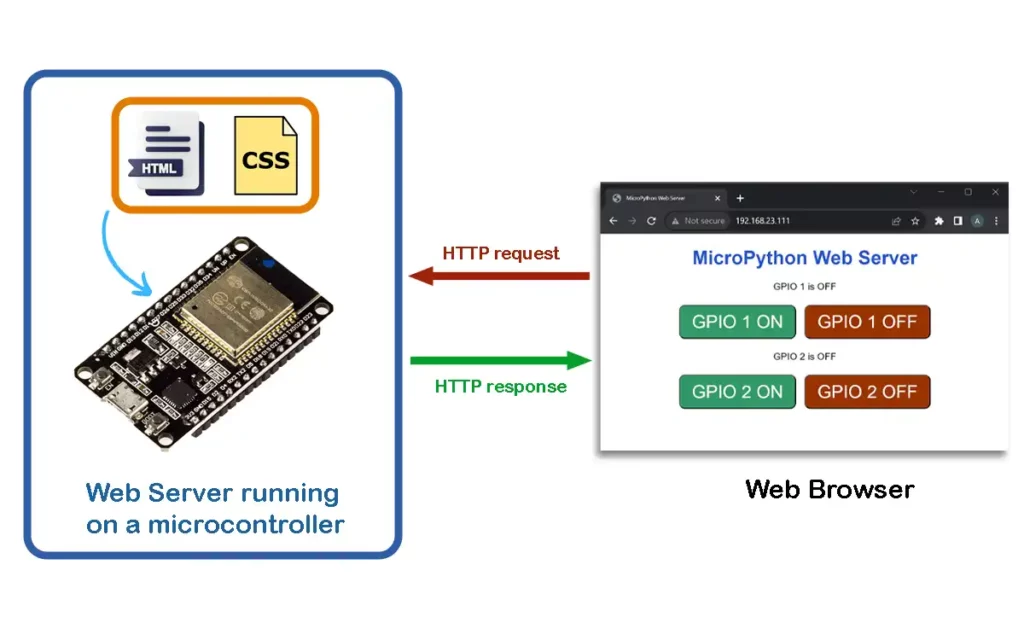 So, a web server running on a microcontroller helps to communicate and exchange information with other devices, typically through a web browser.
This can be used for remote monitoring and control.
For example, you might access the settings of a smart thermostat or a network-connected sensor through a web browser.
Behind the scenes, a web server will handle the communication and serve the requested web pages.
So, a web server running on a microcontroller helps to communicate and exchange information with other devices, typically through a web browser.
This can be used for remote monitoring and control.
For example, you might access the settings of a smart thermostat or a network-connected sensor through a web browser.
Behind the scenes, a web server will handle the communication and serve the requested web pages.
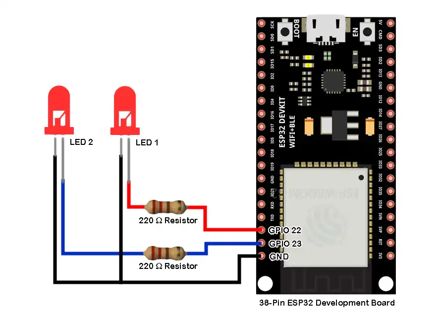 Make sure to use proper current limiting resistors with the LEDs.
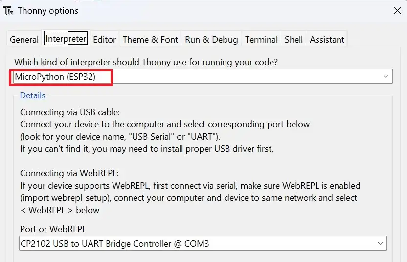 Create a new file by clicking on
 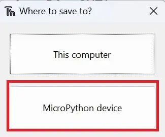 Set the filename as
 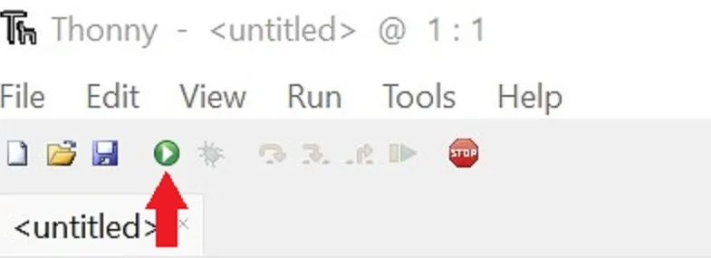 If you face an error while running the script, refer to the troubleshooting section below.
Thereafter you must see some information in the shell of Thonny IDE.
The output messages will help you to know if a proper connection is established.
If you face an error while running the script, refer to the troubleshooting section below.
Thereafter you must see some information in the shell of Thonny IDE.
The output messages will help you to know if a proper connection is established.
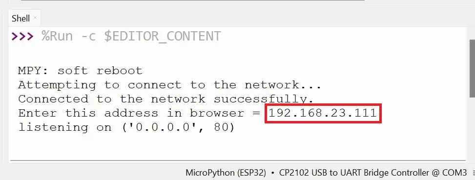 When a connection is successfully established, you will be presented with an IP address.
This IP address has to be entered in a browser connected to the same network.
When you enter the IP address in a browser, you should see the webpage as shown below.
When a connection is successfully established, you will be presented with an IP address.
This IP address has to be entered in a browser connected to the same network.
When you enter the IP address in a browser, you should see the webpage as shown below.
 When we click a button on the webpage, an HTTP request will be made.
For example, if we click the button to switch on GPIO1, the request will be like – 192.168.xx.xx//GPIO1/on.
This can be seen below in the screenshot taken after clicking on the button ‘GPIO 1 ON’.
When we click a button on the webpage, an HTTP request will be made.
For example, if we click the button to switch on GPIO1, the request will be like – 192.168.xx.xx//GPIO1/on.
This can be seen below in the screenshot taken after clicking on the button ‘GPIO 1 ON’.
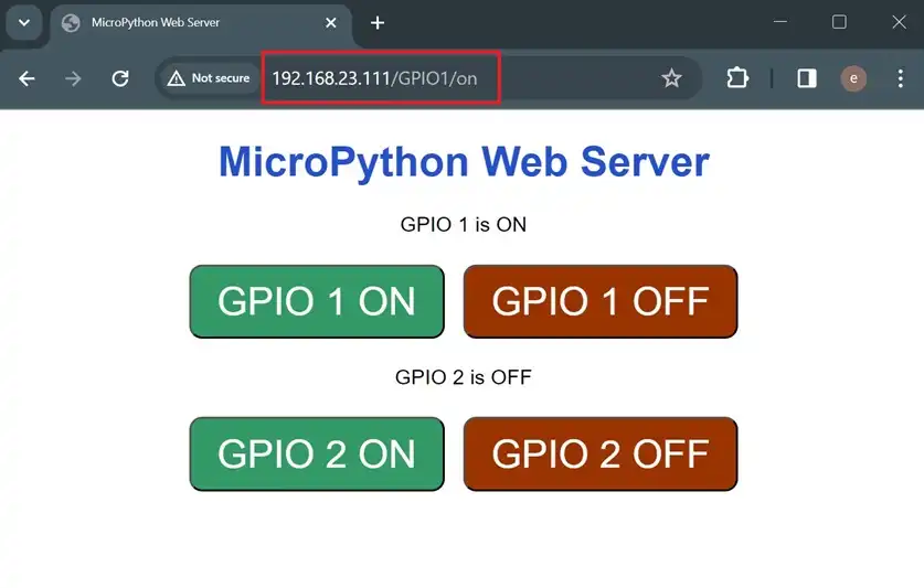 Similarly, each button click will send a unique request, and in response, the status of the toggled GPIO will also be displayed on the webpage.
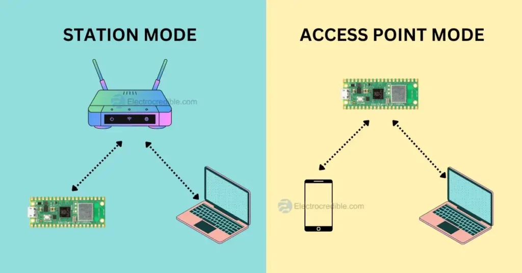
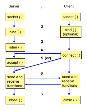

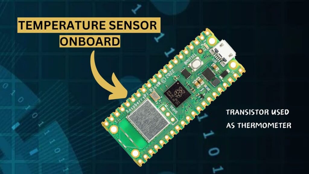
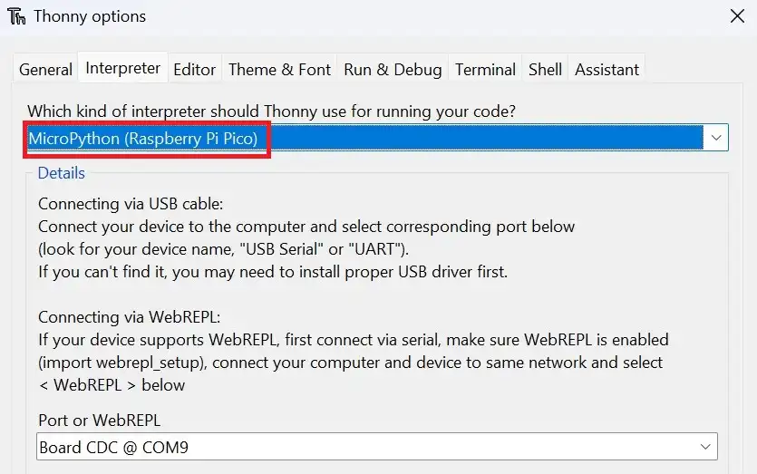 Create a new file by clicking on
 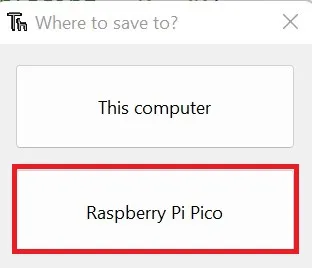 Set the filename as
 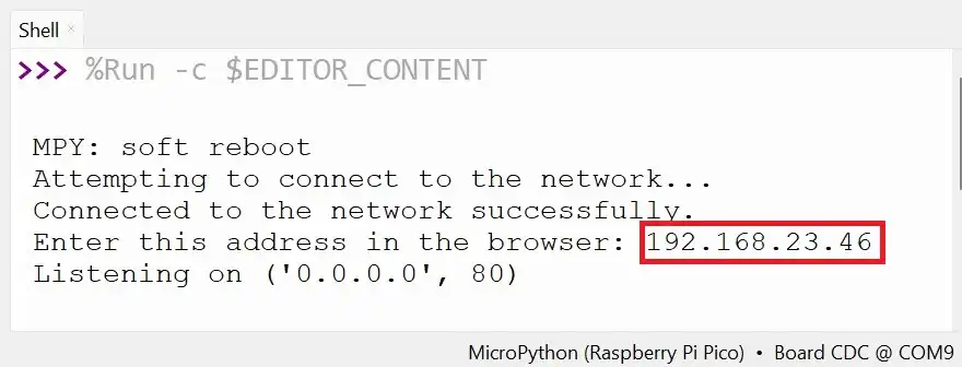 When you enter the IP address, you should see the webpage below.
The webpage should display the temperature data in the Celcius and Fahrenheit scale.
When you enter the IP address, you should see the webpage below.
The webpage should display the temperature data in the Celcius and Fahrenheit scale.
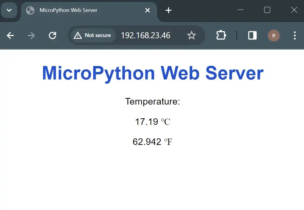
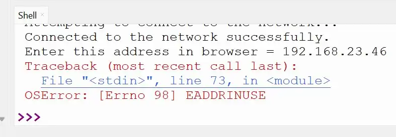 This is due to how TCP/IP network stack connections are managed.
A socket is a combination of an IP address and a port number.
There is a timeout of around 30 and 120 seconds for reuse of a particular socket.
This helps in keeping the connection robust to mitigate packet-related problems.
You can read more about this error in this thread in the MicroPython forum.
When this error shows up, you can try to
reset Raspberry Pi Pico or ESP32(by pressing the reset button), or disconnect and reconnect the USB cable physically.
After entering the IP address in a browser, if you do not see any webpage, then recheck that you are connected to the same network on both devices.
This is due to how TCP/IP network stack connections are managed.
A socket is a combination of an IP address and a port number.
There is a timeout of around 30 and 120 seconds for reuse of a particular socket.
This helps in keeping the connection robust to mitigate packet-related problems.
You can read more about this error in this thread in the MicroPython forum.
When this error shows up, you can try to
reset Raspberry Pi Pico or ESP32(by pressing the reset button), or disconnect and reconnect the USB cable physically.
After entering the IP address in a browser, if you do not see any webpage, then recheck that you are connected to the same network on both devices.
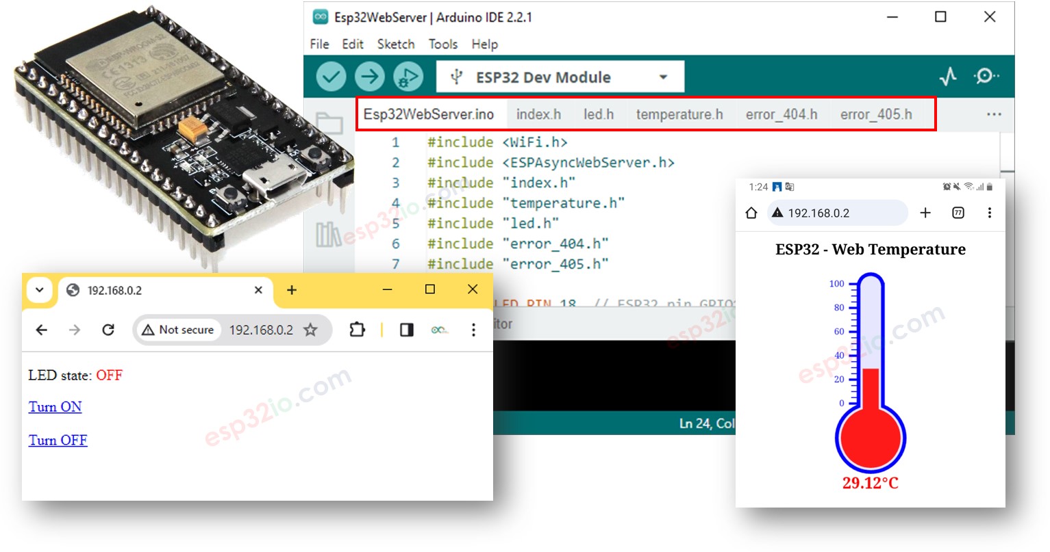
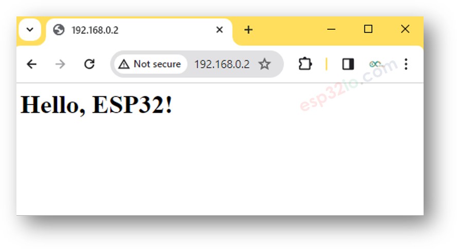
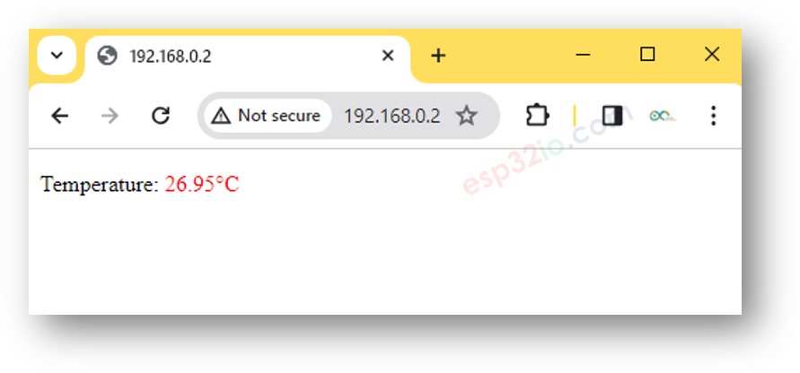 To make the web page look fantastic with a graphic user interface (UI), check out the final section of this tutorial.
※ NOTE THAT:
With the code provided above, to get the termperature update, you have to reload the page on the web browser.
In a next part, we will learn how to make web page update the temperature value on backround without reloading the webpage.
To make the web page look fantastic with a graphic user interface (UI), check out the final section of this tutorial.
※ NOTE THAT:
With the code provided above, to get the termperature update, you have to reload the page on the web browser.
In a next part, we will learn how to make web page update the temperature value on backround without reloading the webpage.
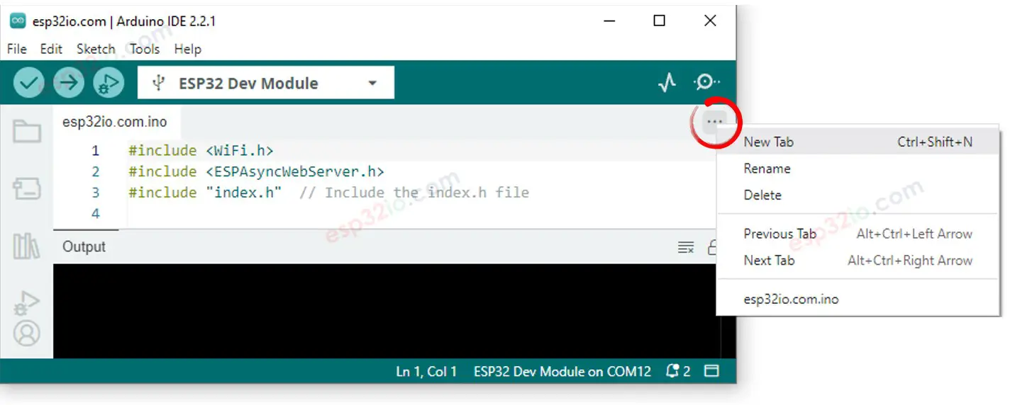 Either click on the button just below the serial monitor icon and choose New Tab, or use Ctrl+Shift+N keys.
Give file's name index.h and click OK button
Either click on the button just below the serial monitor icon and choose New Tab, or use Ctrl+Shift+N keys.
Give file's name index.h and click OK button
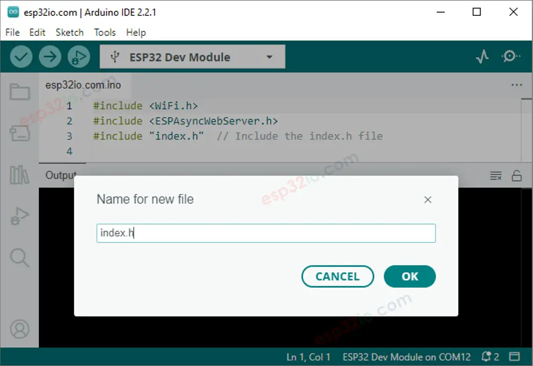 Copy the below code and paste it to the index.h.
/*
* This ESP32 code is created by esp32io.com
*
* This ESP32 code is released in the public domain
*
* For more detail (instruction and wiring diagram), visit https://esp32io.com/tutorials/esp32-web-server
*/
#ifndef WEBPAGE_H
#define WEBPAGE_H
const char* webpage = R"=====(
REPLACE_YOUR_HTML_CONTENT_HERE
)=====";
#endif
Replace the line REPLACE_YOUR_HTML_CONTENT_HERE by your HTML content you prepared before.
There is no problem with new line character.
The below is an example of index.h file:
/*
* This ESP32 code is created by esp32io.com
*
* This ESP32 code is released in the public domain
*
* For more detail (instruction and wiring diagram), visit https://esp32io.com/tutorials/esp32-web-server
*/
#ifndef WEBPAGE_H
#define WEBPAGE_H
const char* webpage = R"=====(
<!DOCTYPE html>
<html>
<head>
<title>ESP32 Temperature</title>
</head>
<body>
<h1>ESP32 Temperature</h1>
<p>Temperature: <span style="color: red;"><span id="temperature">Loading...</span> ℃</span></p>
<script>
function fetchTemperature() {
fetch("/temperature")
.then(response => response.text())
.then(data => {
document.getElementById("temperature").textContent = data;
});
}
fetchTemperature();
setInterval(fetchTemperature, 4000); // Update temperature every 4 seconds
</script>
</body>
</html>
)=====";
#endif
Now you have the code in two files: esp32io.com.ino and index.h
Click Upload button on Arduino IDE to upload code to ESP32
Access the web page of ESP32 board via web browser as before.
You will see it as below:
Copy the below code and paste it to the index.h.
/*
* This ESP32 code is created by esp32io.com
*
* This ESP32 code is released in the public domain
*
* For more detail (instruction and wiring diagram), visit https://esp32io.com/tutorials/esp32-web-server
*/
#ifndef WEBPAGE_H
#define WEBPAGE_H
const char* webpage = R"=====(
REPLACE_YOUR_HTML_CONTENT_HERE
)=====";
#endif
Replace the line REPLACE_YOUR_HTML_CONTENT_HERE by your HTML content you prepared before.
There is no problem with new line character.
The below is an example of index.h file:
/*
* This ESP32 code is created by esp32io.com
*
* This ESP32 code is released in the public domain
*
* For more detail (instruction and wiring diagram), visit https://esp32io.com/tutorials/esp32-web-server
*/
#ifndef WEBPAGE_H
#define WEBPAGE_H
const char* webpage = R"=====(
<!DOCTYPE html>
<html>
<head>
<title>ESP32 Temperature</title>
</head>
<body>
<h1>ESP32 Temperature</h1>
<p>Temperature: <span style="color: red;"><span id="temperature">Loading...</span> ℃</span></p>
<script>
function fetchTemperature() {
fetch("/temperature")
.then(response => response.text())
.then(data => {
document.getElementById("temperature").textContent = data;
});
}
fetchTemperature();
setInterval(fetchTemperature, 4000); // Update temperature every 4 seconds
</script>
</body>
</html>
)=====";
#endif
Now you have the code in two files: esp32io.com.ino and index.h
Click Upload button on Arduino IDE to upload code to ESP32
Access the web page of ESP32 board via web browser as before.
You will see it as below:
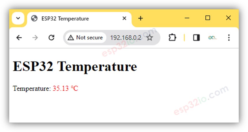 ※ NOTE THAT:
In the above codes:
The HTML code is designed to update the temperature in the background at regular intervals, currently set to every 4 seconds in the code.
This means that the temperature value is automatically refreshed without the need to manually reload the webpage.
You can adjust the update interval in the code to suit your preferences.
ESP32 code serves two requests from the web browser.
One request to return the HTML content of the webpage
The other to return the temperature value requested by the webpage on the backround
For a more comprehensive and detailed illustration, please refer to the ESP32 - DS18B20 Temperature Sensor via Web tutorial
※ NOTE THAT:
If you make changes to the HTML content within the index.h file but don't modify anything in the esp32io.com.ino file, the Arduino IDE won't refresh or update the HTML content when you compile and upload the code to the ESP32.
To force the Arduino IDE to update the HTML content in this situation, you need to make a modification in the esp32io.com.ino file.
For example, you can add an empty line or insert a comment.
This action triggers the IDE to recognize that there have been changes in the project, ensuring that your updated HTML content gets included in the upload.
※ NOTE THAT:
In the above codes:
The HTML code is designed to update the temperature in the background at regular intervals, currently set to every 4 seconds in the code.
This means that the temperature value is automatically refreshed without the need to manually reload the webpage.
You can adjust the update interval in the code to suit your preferences.
ESP32 code serves two requests from the web browser.
One request to return the HTML content of the webpage
The other to return the temperature value requested by the webpage on the backround
For a more comprehensive and detailed illustration, please refer to the ESP32 - DS18B20 Temperature Sensor via Web tutorial
※ NOTE THAT:
If you make changes to the HTML content within the index.h file but don't modify anything in the esp32io.com.ino file, the Arduino IDE won't refresh or update the HTML content when you compile and upload the code to the ESP32.
To force the Arduino IDE to update the HTML content in this situation, you need to make a modification in the esp32io.com.ino file.
For example, you can add an empty line or insert a comment.
This action triggers the IDE to recognize that there have been changes in the project, ensuring that your updated HTML content gets included in the upload.