MustWatch
how2electronics Convert LED Lamp to Smart Lamp 找电线的断点 电烙铁氧化变黑不沾锡 Quick Tips #6 : Measuring High Voltages 體感震動椅 維修移動電源 低成本微型熱像儀 MicroPython: Motor Control DC motors 关键信号布线 自制闪光灯 去除地环路干扰 7段数码管DIY 集成式收发器支持实现小型相控阵雷达平台激光扫描仪的应用
激光器——用于通过辐射受激发射来放大光线器件的缩写——是一种能发出一束或多束相干光的电子装置。 相干表示频率和波形相同、相位差不变的电磁波。 激光可用于:切割、蚀刻、焊接和切片应用——如精密雕刻、钻孔、半导体精加工、机械表面再修复以及(医疗领域的)LASIK 眼科手术。 成像和投影——如全息、共聚焦显微镜、高清晰度测量(用于创建点云)、激光光谱。 数据传输——如条形码阅读器以及光纤和 DVD 技术。 定位——如工作单元安防系统、3D 打印和光探测与测距 (LiDAR) 系统。 激光扫描——使用扫描或偏转激光束阵列——是许多此类应用的核心。 本文将回顾几种工业自动化领域最常见的激光扫描应用。 在最简单的实施方案中,激光信号作为点光源产生,然后通过精确控制的内部镜面反射扫过一个活动角度。 内部光探测器读取反射信号。 由于激光束的投射角和飞行时间 (ToF)已知,扫描仪的电子装置可以使用返回信号来构建扫描范围内的详细结构图。 虽然概念简单,但要使激光扫描技术在现实世界中发挥作用,就必须克服一系列开发难题。 其中更具挑战性的是环境光变化、平台移动、实现一致输出所需的光源校准,以及耐受工业环境中的灰尘和污垢。 我们已经找到了应对这些技术挑战的办法;现在,最复杂的一些应用是地面自主车辆 (AGV) 所采用的 360˚ 3D 扫描。 今天,建筑业中使用自流平激光扫描仪进行精密挂板或地面找平也是很常见的应用。 然而,激光扫描仪的另一个应用则是经纬仪测量,帮助土木工程师将道路等级规划到毫米级分辨率。 这些都是针对特殊功能专门设计的激光扫描设备例子——尽管激光扫描仪的真正用途是在工厂车间。工业安全激光扫描仪
我们来考虑自动化领域中一个重要的激光扫描应用——保护危险工作单元。 在基本装置中,激光扫描仪的位置固定,同时激光扫过一个平面。 这种扫描仪用作安全监控系统的光幕。 光幕应安装在一个能够保护危险性设备上特定部分的位置,并监视任何光束中断。 响应中断时,光幕会使关键设备上的部件减速或停止,或提供报警信号。 必须将扫描仪定位,且激光束的几何形状必须能够监测任何可能的操作者进入点。 正如上述响应模式所暗示的那样,扫描仪通常与其他安全设备(防护装置、警报器和截止开关)配套使用,以确保操作人员在接近设备时不会受到伤害。 在光学扫描技术出现之前,采用机械联锁方式来保障危险工作单元的安全。 在维修期间,工作单元的电源切断并采取上锁挂牌措施。 众所周知,人类是最不可靠,因为有些人总会绕过防护设施。 光学互锁更可靠——特别是与硬复位或双操作控制面板配合使用时,用来确保单人操作不会启动重启功能。 如需详细了解,请参阅 Digi-Key 文章《安全激光扫描仪保护操作者》。用于 AGV 和定位任务的激光扫描仪
现在,我们考虑下在移动平台上使用 ToF 的、基于激光扫描仪的光探测和测距 (LiDAR) 技术的优缺点。 用于自主地面车辆 (AGV)中时,此类系统依赖 AGV 定位的内部地图,因此所有物体探测都上下关联。 这种能力被称为同步定位和映射或 SLAM。 这会增加系统复杂性,因为位置定位误差会直接影响障碍物或目标的映射定位。 使用本地应答器、教学编程或地板嵌入式轨道有助于缓解这一问题。AGV 中 LiDAR 的电气和机械注意事项
LiDAR 正在持续发展,其主要推动力自自动驾驶汽车市场。 因此,在性能、功能、价位上都存在很大差异。 这也意味着目前还没有出现安装或连接标准。 当考虑在应用中使用 AGV 时,这个过程就是将现有的产品与系统要求相匹配,并从中指定物理结构。 目前,有几家公司可进行系统设计,提供完整的或可定制 LiDAR 系统。 根据不同的需求,预先设计的解决方案可能只是形成更优化解决方案的起点。 美国国家标准与技术研究所 (NIST) 率先制定了 AGV 安全标准。 目前这些标准主要集中在碰撞方面上,具体包括:折叠式保险杠:在多数老款车型中,保险杠将包含力检测功能,并在撞上障碍物时启动停车功能,限制碰撞接触力。 非接触方法:现代 AGV 应能探测到物体,并在不造成碰撞的情况下停车。 在测试时已使用了近似于人形的测试物,不过仍建议在未来的测试中更多地使用类似于人形和姿势的测试物。 突然出现的障碍物:安全区域内突然出现的障碍物。 预计 AGV 会启动紧急停车,然而并不期待避免发生碰撞。 预测被遮挡的障碍物:这些障碍包括 AGV 车道附近的设备或人员。 预计在与 AGV 车道的间隙小于 0.5 m 的地方会有指定的慢速区。 在预测未来 AGV 的使用过程中,他们还会制定机器人安全标准,以便开始研究各种测试方法,其中会涉及到 AGV 底盘固定的机械臂。 LIDAR 领域的主流趋势之一就是在不牺牲性能的前提下,推动激光雷达体积、重量和成本的降低。 这在过去十年取得了进展,使这些属性已减少了一个数量级。 我们前文提到,SLAM 或者本地化越来越受关注。 理想的解决方案是,AGV 能够从任何地方出发并绘制用于行驶时参照的自用内部世界地图。 执行此类任务需要依赖 LIDAR 与包括 GPS、轮速传感器和摄像头在内的其他类型传感器的集成。激光扫描仪用于数据通信
线性条形码扫描仪的概念很简单:一种由线条和空格组合而成且读取方便的摩斯码。 测量由扫描仪发出并由条形码反射回的光线。 测量反射回的环境光根据应用的不同,全球常用线性条形码有九种。 虽然激光扫描仪是条形码扫描的主流,但条形码不一定需要激光光源的精度,下面就是一些例外。 大多数情况下,条形码内容的读取和翻译都是在扫描仪内部完成。 通常,条形码扫描仪将解码后的值直接发送至数据库。 少数领域要求条形码激光仪具有高分辨率。 对于空间受限的地方,标准条形码带的物理标准较窄。 这就需要高分辨率扫描仪,激光扫描仪恰好满足这一条件。 条形码距离较远时也存在类似情况(比如在如仓库货架上),这会有效地减小代码角度。 有时,环境光不足以保证条形码与空间之间具有良好对比度。 这种情况下,类似激光这样的已知光源就适合用来照射代码,使其易于阅读。 即使是经常逛杂货店的消费者,也很熟悉自助收银台使用的手持扫描仪。 因为条形码扫描能从无限多的方向进行,所以扫描仪在这些设置中必须产生紧密交叉的激光扫描线矩阵。 这就保证了无论条形码如何呈现,至少有一条扫描线会截取全部代码。- 扫描仪在哪里使用?用于仓库盘点、生产线上生产零件的跟踪,还是用于销售点?需要多少数据、物品上有多大物理空间用来粘贴条形码?在什么表面上打印条形码——以及该表面能够保持多高的打印分辨率?
关于激光扫描仪应用的结论
自 1960 年发明激光以来,基于激光的设备和用途便一直层出不穷,令人瞠目结舌。 虽然条形码比激光早 11 年,但通过相干光扫描读取信息已成为黄金标准。 基于激光的位置跟踪和检测扫描也已经成为工业领域的常用解决方案。 对大多数工业制造和跟踪应用而言,无论是从零开始设计系统还是改进现有工艺,激光扫描方法的某些变化可能是极有价值的。 考虑到技术已发展到现在的地步,如果现在还没有确切的配置,那么就会有一些非常适合的东西出现。RS-485
RS-485概述RS-485和RS-232一样,都是串行通信标准,现在的标准名称是TIA485/EIA-485-A,但是人们会习惯称为RS-485标准,RS-485常用在工业、自动化、汽车和建筑物管理等领域。 RS-485总线弥补了RS-232通信距离短,速率低的缺点,RS-485的速率可高达10Mbit/s,理论通讯距离可达1200米;RS-485和RS-232的单端传输不一样,是差分传输,使用一对双绞线,其中一根线定义为A,另一个定义为B。BLDC Motor Control: Sensorless Brushless DC Motor Controllers
A Quick Review of Brushed and Brushless DC Motors Brushless DC (BLDC) motors have become extremely popular over their predecessor, the brushed DC motor (see figure below). As the name implies, "brushed" DC motors use brushes, and a commutator, for controlling the movement of the motor's rotor. Figure 1. Brushed DC motors use brushes and a commutator.
Again, as implied by its name, brushless DC motors don't utilize brushes; motor movement is controlled by means of carefully designed drive signals.
Compared to brushed motors, brushless motors offer improved reliability, longer life, smaller size, and lower weight.
BLDC motors have become more popular in applications where efficiency is a critical concern and, generally speaking, a BLDC motor is considered to be a high-performance motor capable of providing large amounts of torque over a wide speed range.
Some BLDC motors use Hall-effect sensors for detecting the position of the motor's rotor with respect to the motor's stator (see Figure 2 below).
 Figure 2. BLDC motor using Hall-effect sensors.
Image courtesy of Nidec.com.
Other motors don’t have sensors; they’re referred to as sensorless BLDC motors.
In place of using Hall-effect sensors for determining the rotor's position and/or speed, a phenomenon called back EMF is employed (see Figure 3 below).
 Figure 3. Sensorless BLDC motor control using back EMF.
Image courtesy of Microchip (page 4).
Sensorless BLDC Motor Control
Sensorless BLDC motor control—sometimes called sensorless trapezoidal control of BLDC motors—uses back EMF (BEMF) for determining the location of the motor's rotor (the motor's rotating part) with respect to the motor's stator (the stationary part). A voltage applied across a motor's winding forces the motor's rotor to turn. The movement of the rotor through the motor’s magnetic field, however, is analogous to the behavior of a generator, and consequently the motor not only receives an applied voltage but also generates its own voltage. This voltage is referred to as back electromotive force, or back EMF, and it is proportional to the motor's rotational speed. Back EMF can be used to determine a motor's rotor speed and position—no sensors are required. Controlling a motor by means of back EMF is not a simple task; most sensorless BLDC motors are controlled using a microcontroller, a digital signal processor, or a dedicated driver IC. The figure below shows a typical sensorless BLDC motor driver. Figure 4.Typical sensorless BLDC motor drive.
The DRV10983 from Texas Instruments is a three-phase sensorless motor driver with integrated power MOSFETs capable of providing a continuous drive current of up to 2 A.
It is highly integrated and requires few external components.
 Figure 5. TI's DRV10983 Sensorless BLDC motor control driver.
Image courtesy of Texas Instruments (page 1).
Not all sensorless BLDC motor controllers have integrated MOSFETs.
Consider, for example, the A4964 from Allegro.
This part requires the use of external N-channel power MOSFETs; it can operate in conjunction with a microcontroller or as an independent single-chip motor controller.
 Figure 6. Allegro's A4964 sensorless BLDC controller can operate either with a microcontroller or as an independent motor controller.
Image taken from the A4964 datasheet.
As mentioned earlier, the term trapezoidal is sometimes used when describing sensorless BLDC motor controllers.
And when viewing the figure below, it's easy to see why: the voltage waveforms for each of the three motor phases have a trapezoidal shape.
 Figure 7. Microchip's AN970 showing Hall-effect sensor waveforms and corresponding back-EMF trapezoidal waveforms.
Image courtesy of Microchip (page 3).
Disadvantages of Sensorless BLDC Motor Controllers
When the rotor of a sensorless BLDC motor is rotating, its sensorless scheme can work perfectly. However, this is not the case when the motor's rotor is stationary, and this leads us to one major disadvantage of using sensorless BLDC motors. When the motor's rotor is not turning, no back EMF generated. Without back EMF, the drive circuitry lacks the information it needs to properly control the motor. For this problem, Texas Instruments offers two solutions as stated in their DRV10983 datasheet (page 17): Use the DRV10983's initial position detect (IPD) feature to determine the rotor position "based on the deterministic inductance variation, which is often present in BLDC motors." Or, use the align-and-go technique. With this method, a voltage is applied across one of the phases to force the rotor into a known alignment. Another disadvantage of using sensorless BLDC motors is related to the relationship between back EMF and angular speed. Lower speed means less back EMF, and consequently Hall-effect BLDC motors might be more effective than sensorless BLDC motors in low-speed applications.In Conclusion
Brushless DC motors offer significant advantages over standard brushed motors. Brushless DC implementations can be sensorless or based on Hall-effect sensors integrated into the motor (a third option is the use of an external angular position sensor). Sensorless systems reduce cost and require fewer interconnects between the driver module and the motor; they can be somewhat complex, but high-performance integrated circuits help to simplify the design task. Though sensorless systems are usually preferable, the use of Hall-effect sensors may be a better choice for low-speed applications.逆变H桥IGBT单管驱动+保护
IGBT单管相当的脆弱,同样电流容量的IGBT单管,比同样电流容量的MOSFET脆弱多了,也就是说,在逆变H桥里头,MOSFET上去没有问题,但是IGBT上去,可能开机带载就炸了。 这一点很多人估计都深有体会。 当时我看到做鱼机的哥们用FGH25N120AND这个,反映很容易就烧了,当时不以为然。 只到我在工作中遇到,一定要使用IGBT的时候,我才发现我错了,当初我非常天真的认为,一个IRFP460,20A/500V的MOSFET,我用个SGH40N60UFD40A/600V的IGBT上去怎么样也不会炸的吧,实际情况却是,带载之后,突然加负载和撤销负载,几次下来就炸了,我以为是电路没有焊接好,然后同样的换上去,照样炸掉,这样白白浪费了好多IGBT。 后来发现一些规律,就是采用峰值电流保护的措施就能让IGBT不会炸,下面我就会将这些东西一起详细的说一说,说的不好请大家见谅,这个帖子会慢慢更新,也希望高手们多多提出意见。 我们将这个问题看出几个部分来解决:1,驱动电路;2,电流采集电流;3,保护机制;一、驱动电路这次采用的IGBT为IXYS的,IXGH48N60B3D1,详细规格书如下:IXGH48N60B3D1驱动电路如下:增加電池能量
要增加蓄電池能夠儲存的能量,需要增加電池中在正極和負極之間移動的金屬離子的數量。 蓄電池也是通過離子從正極向負極移動來儲存電能。 如果增加金屬離子的數量,即可使蓄電池獲得高容量,但正極能保持的離子的數量存在極限,這成為蓄電池開發的障礙。 如果讓氧原子擁有的電子也成為能量的搬運工,即可飛躍式增加能儲存的能量。 這一思路以往就有,但存在利用氧原子的電子的材料容易發熱這一缺點。 失去電子的氧原子由於結構變得不穩定,將與附近的氧原子結合。 這時就會産生熱量並失去儲存的能量。 這一點成為實用化的障礙。 由鈉、錳和氧混合而成的名為「Na2Mn3O7」的材料。 如果將這種材料用於蓄電池的正極材料,即使讓氧原子的電子成為能量的搬運工,氧原子之間也不會在正極電極相互結合。天线增益、发射角、阵列
 一、关于增益:
电波是一种能量,根据能量守恒定律,高增益天线并不是把电波的总能量增强了,而是把电波集中到较窄的某一空间,在该空间的电波密度得到加强。
低增益天线把电波散射到较广的空间。
最合适的比喻就是手电筒,天线相当与手电筒的反射镜,调整手电筒反射镜,可能让光线聚焦在一个较小的点上,你会发现被照射的这个点很亮,但周边比较暗,适合看较远物品,视野窄;把手电筒调到散光状态,周边光线强度都比较平均,适合看近距离物品,视野广。
光波能量守恒,在同一条件下,手电筒的反射镜并没有改变灯泡的自身的发光亮度。
电波的也一样,天线并没有改变发射机的功率,更加没有放大发射机的功率。
二、关于发射(仰)角
1、短波
天线的发射角主要包括水平发射角和垂直发射角,在这一小节,我们只讨论水平发射角(也就是我们短波通信中常叫的“发射仰角”)。
短波通联,要玩的痛快,就必须掌握发射仰角与波瓣一些常识,楼主已经分析的很透彻,在这里用通俗的方式描述一下,天线发射仰角越小,通过电离层一次发射跳跃的距离越远,适合远距离通信,一般情况下,发射仰角小于30度的天线适合远距离DX通信,如高架设的多单元短波八木天线,但近距离通信会出现盲区,这类天线不适合国内(省内)通联。
我们会发现,国内通联,高发射仰角的倒V天线,综合效果往往会比高增益的八木天线效果好,斜拉天线仰角更大,通常500公里以内的短波无盲区通信会使用。
我的个人经验:发射仰角的30-60度的适合国内中短距离通联,发射仰角的小于30度的适合远距离DX,发射仰角的小于20度的,适合猎奇,如南美东岸。
天线架设高度与发射仰角(增益)有很大关系,默认情况,天线的设计增益参考高度都是1/2波长高度,比如,一个设计发射仰角为25度(增益为12dbi)的对数周期短波天线,如果架设高度只有1/4波长高度,发射仰角可能会变成40度,增益也会降到大概9dbi;如果架设高度达到1个波长高度,发射仰角可能会变成小于20度,增益也会增加到13dbi以上。
条件好的比赛基地,通常会使用可升降塔来安装定向天线,这样不单是因为防风的问题,更主要因数是参赛者可以按照通联的目的地距离,升降天线高度,来改变天线增益和发射仰角,达到通联不同地区的目的。
关于波瓣,楼主说的非常清晰了,通常,短波天线的架设高度和波瓣数量有很大关系,架设高度大于1/2波长时,波瓣会增加,大于1个波长时,波瓣会变的尖锐,多个尖锐波瓣对于DX主叫是一件好事,通常会有很好的收获,滩主很容易就做成了,这种方式我们通常笑话是“对多个特定地区播种”。
多波瓣分为水平多波瓣和垂直多波瓣,这里就不再深入了。
2、超短波(U/V段)
在U/V段,通常采用垂直极化方式,视距传播,发射角一般有两个含义,一是水平发射角、一个是垂直发射角。
全方向的GP天线垂直发射角是360度,水平发射角因为增益不同而不同,增益越大,水平发射角越小,假如是一个增益10dbi的玻璃钢天线,水平发射角大约是25度,U/V段GP天线主要通过改变水平方向上的电波密度,实现改变增益。
对数周期天线具有较强的方向性,垂直发射角跟对数周期天线的单元数目关系最大,水平发射角次之,一个12单元的U段八木,垂直发射角发射角大约是30度,水平发射角35度,U/V段对数周期天线主要通过改变垂直方向上的电波密度,实现改变增益。
对于使用U/V段中继,了解垂直发射角与水平发射角非常有必要。
架设在城市高楼的中继台,为了确保中短距离的中继效果,一般会选择较低增益的玻璃钢天线(约6DBI),因为低增益GP天线的水平发射角较大,减少了近距离中继盲区。
一般高山中继会采用高增益玻璃钢天线(大于10DBI),较小的水平发射角,满足了中远距离的中继通信需要。
对于使用中继的电台,天线的选型也一样,经常在中继台5公里范围内上中继的电台,尽量使用低增益,较大水平发射角的天线,如果使用高增益GP天线,会出现中继覆盖盲区,效果反而会变差。
对于经常使用30公里以上远程中继的电台,建议使用高增益的天线。
三、关于天线阵
兜了一个大圈,才回到本贴主题,简直是唐僧再世。
先来看看天线阵的几种组阵方法:
1、等幅并行馈电组阵:
用于同一指向、同一结构的天线组阵,各单元天线输出的功率相同、相位相同,同方向的增益加大,这是我们业余无线电常用的组阵方法。
2、中央串行馈电组阵:
用于同一结构的天线组阵,各单元天线的功率和相位对应,用于分解承受大功率,如电视发射塔天线、雷达天线等。
3、总线馈电组阵:
用于多个方向天线组阵,各单元天线的功率和相位不同,可以根据控制系统进行分配。
再来看看我们生活应用最广的天线阵:
1、电视信号接收天线阵:
我们要接收不同方向电视发射站的信号,往往需要多个不同方向的八木天线接收,通过合路器连接到电视机,往往还包括VHF、UHF不同频率的天线进行合路,最典型的案例就是在深圳了,周遍各方向有数十个电视发射站信号,包括深圳、香港、珠三角等地。
在我们工作室,要接收时下最流行的地面数字高请电视,我使用三个八木天线进行合路,一个7单元水平极化八木天线接收深圳台节目(正东方向,706MHZ);用了一个5单元垂直极化八木天线接收央视高清节目(正东方向,786MHZ,真不明白电视台采用垂直极化发射的目的,估计不想太多人看到,影响有线电视的生意);用了一个3单元4阵列的水平极化八木阵(同方向中央串行馈电组阵)用于接收香港高清信号(东南方向,586、602、650MHZ)。
三个天线合路到一个数字接收机,苦难重重,两个或三个天线可能同时接收到同一发射站信号,出现信号抵消想象,采用了物理隔离办法(阻挡非接收方向)、滤波隔离(只允许某一频率通过),终于把能收到的22个地面无线高清节目通过一根馈线全部拿下。
这个小试验,是一个大的“总线馈电”天线阵中还包括了一个“串行馈电”子天线阵,可以看出采用“总线馈电组阵”的难度比较大,影响因数比较复杂。
2、蜂窝移动电话天线阵:
蜂窝移动是贝尔实验最伟大的发明,改变了整个世界的生活方式,蜂窝移动电话系统的核心之一就是数字控制天线阵,整个蜂窝系统其实就是一个庞大的数以万计的蜂窝天线阵,这是一项非常成熟的应用技术,在这里,我们只简单解剖一下单个基站天线阵的情况。
现在的蜂窝移动基站一般由多个天线组成,每个天线有一定的发射角,有低容量的120度3天线阵基站,也有高容量的60度6天线阵基站,甚至更多的,等等。
360度多天线系统,主要功能有二,一是解决数据通信用户容量问题,二是解决了天线增益与信噪比问题,我们来看看用户位置与基站天线的选择,系统是通过计算机软件控制,根据用户到基站各天线之间的信号强度,电子合路切换,选择所需的天线。
蜂窝移动的天线阵技术虽然很成熟,但要在我们业余无线电里应用,难度还是非常大,假如我们想做一套4个或六个方向的360度覆盖的八木阵,通过计算机,根据来源信号强度来控制所需的收发天线,需要投入资金不是一般个人能承受的。
问题1:用两个4单元八木组成天线阵,指向一个方向。
技术上完全可行,减去功分合路器等中间环节的损耗,会增加大约3dbi的增益,同时发射角变小,波瓣变尖。
相对来说能通到的更远的电台,除此之外,也会带来很多的副作用:一是带宽减小,二是SWR增大,三是阻抗匹配难度增加,四是需要更精准的转向器。
算了一下这笔帐,还不如做一个6单元八木天线来的直接,效果和这个阵列相当,但轻松多了。
以下这些情况使用这种方式,成本很合算:一是八木天线到达一定的单元极限,电性能和物理性能都不允许增加单元了,二是高波段的八木,如6米波、2米波等,阵列难度和成本都很低;三是高带宽的对数周期天线,14-30MHZ对数周期天线要增加3dbi增益,需要增加约2.5倍的材料,而且主梁会过长,物理性能无法保障,所以做成阵列的成本更低。
问题2:用两个4单元八木冲着不同的方向,但是使用一个转向机。
这个问题有点复杂了,在回答这个问题之前,我在上面举了两个例子,电视接收天线阵和蜂窝移动天线阵,要实现不同方向的天线阵合路功分控制,会带来很多的副面影响,只有蜂窝移动通过数字控制技术真正解决了这个问题,我们业余无线电不建议采用这方式,除非你有海量的资金或庞大技术力量,研发出强大的信号分配控制系统。
不过,假如我有两个你那样的八木,尝试一下也不坏。
问题3:想在比赛中通过调整天线系统来加强20米波段的成绩。
这个问题变得简单了,作为比赛电台,最有效的办法是配置一个10至40米电动可升降铁塔,根据通联目的地需求,调整铁塔高度,改变天线增益和仰角,铁塔就是一个天线增益调整器,非常凑效。
电磁炉原理讲解
一、原理简介 电磁炉是应用电磁感应加热原理,利用电流通过线圈产生磁场,该磁场的磁力线通过铁质锅底部的磁条形成闭合回路时会产生无数小涡流,使铁质锅体的铁分子高速动动产生热量,然后加热锅中的食物。氮化镓 相控阵雷达
相控阵雷达的出现可以说是雷达探测技术的一大飞跃; 而有源相控阵雷达又是相控阵雷达中的高端模式。 那么有源相控阵雷达到底强在哪里呢? 有源相控阵雷达可以对几百个目标同时实现全程跟踪与监测。 可以引导导弹同时攻击十几个到几十个最有威胁性的重点目标。 甚至可以对大多数非隐身目标直接三维成像; 并且对真假目标快速识别。 不但对过去传统的空中目标有如此强悍的功能,就是把有源相控阵雷达设置在高空,那么对地面与海面的所有目标也可以实现超快速与超大容量的识别跟踪引导与三维成像。 相控阵雷达的原理很早就被提出; 不过早期的有源相控阵雷达都是电子管体制,如果集成起来则面积与发射总耗电量都相当惊人,只能用作对太空目标的战略预警雷达之用。 是著名的7010工程 7010战略预警雷达历时10年建成,此后又正常运行了另外10年,取得了一批重大成果,曾经在世界上最准确预测了一些核动力卫星的坠落轨迹,震惊全球。 虽然7010工程整体效果尚可,不过到了1990年代以后,全球相控阵技术向高端集成电路发展。 此时最重要的TR发射与接收组件的生产技术国内无法突破。 但是在有源相控阵雷达的整体设计、组件的巧妙布局减重以及软件算法上却居于全球超一流的地位。 于是作为“交换”条件,开始与某军工强国合作研发大型预警机。 并且创造性的提出了:背负式、超大圆盘、三面有源的整体方案,同时也负责算法与主要核心软件的开发。 外方主要提供先进TR组件的生产工艺以及高成品率的品控管理技术。 为以防万一,在与外方合作的同时还在国内开始了并行研发工程。 果不其然,在超级大国的干涉下,与外方的合作被迫中止。 但是自家的并行工程却大获成功,最终被称为“争气机”。 此后则一发不可收拾。 仅仅用不到20年的时间,就把有源相控阵技术彻底推到了全球绝对第一的位置,而且属于搞成了白菜化并且玩出了花。 各种有源相控阵不但陆地空中海上太空无处不在,多的让人眼花缭乱。 甚至在民用灭蚊器上都用上了氮化镓有源相控阵! 所有这一切,有一人居功至伟! 王小谟院士永垂不朽! 王小謨從事雷達研製工作50餘年,先後主持研製過中國第一部三座標雷達等多部世界先進雷達,在國內率先力主發展國產預警機裝備,提出中國預警機技術發展路線圖,構建預警機裝備發展體系,主持研製中國第一代機載預警系統,引領中國預警機事業實現跨越式、系列化發展,並邁向國際先進水平。 氮化镓(GaN)是一种非常坚硬且在机械方面非常稳定的宽带隙半导体材料。 由于具有更高的击穿强度、更快的开关、更高的热导率和更低的导通电阻,氮化镓基功率器件明显比硅基器件更优越。 氮化镓晶体可以在各种衬底上生长,包括蓝宝石、碳化硅(SiC)和硅(Si)。 在硅上生长GaN外延层可以使用现有的硅制造基础设施,从而无需使用成本很高的特定生产设施,而且可采用低成本、大直径的硅晶片。 氮化镓材料用于制造半导体功率器件,也可以用于制造射频元件和发光二极管(LED)。 氮化镓技术展示出它可以在功率转换、射频及模拟应用中,替代硅基半导体技术。 把电子性能提升至另一个更高的水平及使得摩尔定律复活的领先侯选原材料,就是氮化镓材料。 与硅基器件相比,氮化镓器件传导电子的效率可以高出1000倍,而同时比硅器件的制造成本较低。 硅器件的技术发展已经到了极限,而一种新兴并具有较高性能的半导体材料正在冒起–它就是氮化镓半导体。 幸运的是,制造氮化镓器件的成本比制造MOSFET器件的成本为低,这是由于目前用来制造传统硅基半导体的相同工厂中,采用制造硅器件的标准步骤来制造氮化镓器件,从而使得具有相同性能的氮化镓器件的体积可以小型化很多。
由于每个氮化镓器件都比硅基器件小很多,因此每块晶圆可以生产出更多的氮化镓器件,这样,与等效硅基器件相比,制造氮化镓器件的成本就总是更低。
监控摄像头的焦距

 这也导致了很多朋友在选择监控摄像头时非常的纠结,而其中纠结的比较多的一个问题就是如何选择监控摄像头的焦距,这篇文章咱们就来仔细聊聊监控摄像头的焦距选择问题。
一、什么是焦距?
焦距,在光学系统中是指平行光入射时从透镜光心到光聚集之焦点的距离。 也是指监控摄像机中,从镜头镜片光学中心点到摄像机的CCD/CMOS感光元件之间的距离。
 对于监控摄像机来说,这个焦距的大小就决定了拍摄画面的成像大小、视场角大小和景深大小。
视场角:
以镜头为顶点,以观察目标的物像可通过镜头的最大范围的两条边缘构成的夹角。
景深:
指在摄像机镜头能够取得清晰图像的成像时被拍摄物体前后距离范围,简言之,景深就是我们能够看清楚的距离范围。
PS:
景深与摄像机的焦距、镜头光圈和物距也都有关系,焦距只是其中一个因素。

二、不同焦距的效果如何?
现在主流的监控摄像头都是网络监控摄像头,焦距一般为2.8mm、3.6mm/4mm、6mm、8mm、12mm、16mm等,有些还具有变焦功能,那么不同的焦距区别在哪里呢? 简单来说: ✅ 焦距越大,看的越远,视角范围越小; ✅ 焦距越小,看的越近,视角范围越大;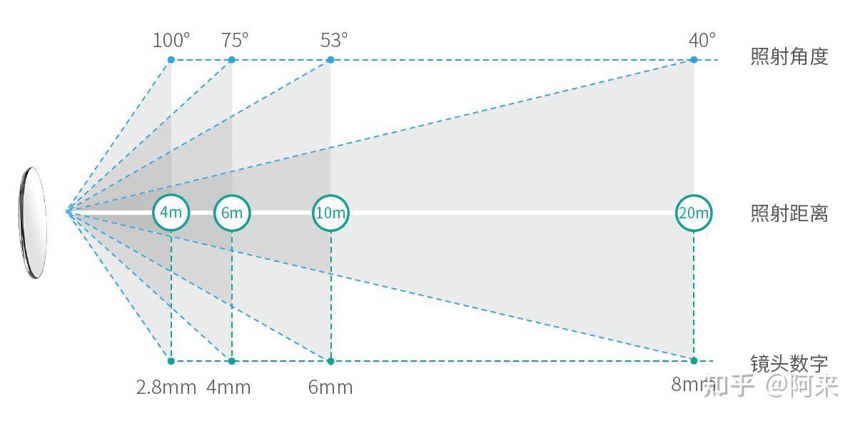 借用网络上的一张焦距效果对比图来做个参考:
 可以看到:
✅ 在同样的距离下(如第一列),焦距越大,能看到的视角范围越小,但是相对细节越清晰。
✅ 在同样的焦距下(如第一行),距离越远,能看到的视角范围越广,但是识别度就越低。
✅ 想要看清人脸或人形,距离越远,需要的焦距越大(斜对角)。
三、如何选择监控摄像头焦距?
前面看了不同焦距的拍摄效果,那实际中监控摄像头的焦距到底该怎么选择呢? 我们可以从以下几个维度考虑:1、监控范围
监控摄像头的焦距决定了监控画面的大小和有效可视距离,也就是监控的范围。 ☆ 对于监控范围较小,取景角度大的情况,如家庭的客厅、小型商铺,可以选择焦距较小的监控摄像头。 比如3.6mm或4mm焦距的摄像头,视角范围可以达到75°-90°,有效监控距离可达5米以上,可以覆盖40²-80²的空间。 ☆ 对于监控范围较大,如10m*10m以上的空间,需要选择焦距较大的监控摄像头。 但是由于焦距大,相应的监控角度就会变小,为了实现完全监控,就需要我们考虑使用云台球机,或者安装多台监控摄像头来保证完全覆盖。 ☆ 对于监控范围固定,但是距离非常远的情况,比如需要监控30米外的停车位,就需要选择更大焦距的摄像头,比如12mm以上的监控摄像头。 下图可以做一个简单的参考: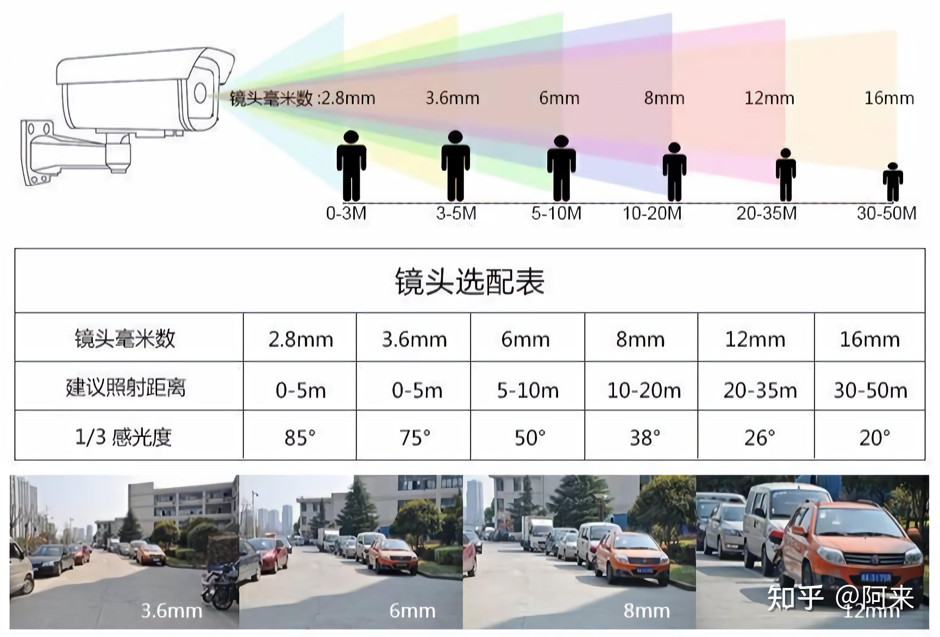
2、使用场景
很多时候,我们选择监控摄像头,都是针对具体的场景需求来的。 如果不想过多了解那些繁琐的焦距参数的话,我们可以粗略的按照下面的使用场景来判断选择摄像头焦距: ✅ 车库、储藏间等狭小空间,建议选择2.8mm焦距,最佳监控距离3m以内 ✅ 家庭室内或小商铺等环境中,建议选择4mm焦距,最佳监控距离3-5m ✅ 家庭庭院、阳台、门口等场景,建议选择6mm焦距,最佳监控距离5-10m ✅ 室外的道路、胡同等场景,建议选择8mm焦距,最佳监控距离10-20m ✅ 某些远距离固定位置的监控,建议选择12mm焦距,最近监控距离为20-30米左右 ✅ 还有一些摄像头镜头是可变焦的,可以根据监控场景范围来调整镜头大小3、实际需求
前面介绍了很多监控摄像头焦距的具体选择方式,都有一个共同的前提: 在能够有效看清人或物的情况下。 而实际中,我们可能关注的点也有些不同,比如: ☆ 有时我们可能不在意是否能看清人或物,我们只需要监控范围足够大,这时就可以选择焦距小如2.8mm的摄像头,还有一些鱼眼摄像头,监控视角甚至能达到180°,镜头前的范围都能一览无余。 ☆ 有时我们可能更在意很远距离下的很小的一片固定区域,比如50米外的固定车位,这时就可以选择16mm以上的摄像头,不求范围,只关注很小一片区域。 ☆ 还有,有时我们需要监控的范围是个狭长的区域,比如5*30m的范围,焦距小的远处看不清,焦距大的近处看不到,我们就可以考虑带双摄甚至三摄变焦功能的摄像头,能够同时兼顾远处和近处的监控。computer keyboard
A computer keyboard consists of many switches, one for each key which you can press. All of these switches are electrically arranged into groups. For discussion purposes, we call these groups rows and columns, but those groups do not physically correspond to the physical location of the key on the keyboard. Below is an example schematic diagram showing how the switches in a specific keyboard were arranged. A special integrated circuit is
 3 Best LED Bulb Circuits
the finalized design
Improving the above Design
Why use LEDs
How the Circuit Functions
High Watt LED Bulb using 1 watt LEDs and Capacitor
Circuit Diagram#2
Surge Controlled Voltage Regulation
Solid State LED Bulb Circuit with Dimmer Control using IC IRS2530D
Introduction
How the LED Controller Functions
Circuit Diagram#3
After doing a lot of research in the field of cheap LED bulbs, I could finally come up with a universal cheap yet reliable circuit that ensures a fail-proof safety to the LED series without involving costly SMPS topology.
Improving the above Design
Why use LEDs
How the Circuit Functions
High Watt LED Bulb using 1 watt LEDs and Capacitor
Circuit Diagram#2
Surge Controlled Voltage Regulation
Solid State LED Bulb Circuit with Dimmer Control using IC IRS2530D
Introduction
How the LED Controller Functions
Circuit Diagram#3
the finalized design
⇧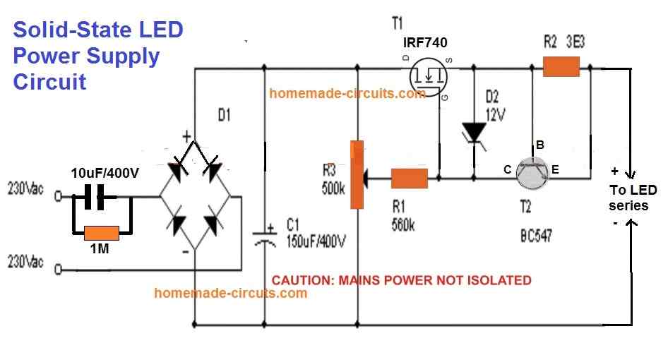
 You just have to adjust the pot to set the output according to the total forward drop of the LED series string.
Meaning, if the total voltage of the LED series is say 3.3V x 50nos = 165V, then adjust the pot to get this output level and then connect it with the LED string.
This will instantly illuminate the LEDs at full brightness and with complete over voltage and over current or surge inrush current protections.
R2 can be calculated using the formula:
 Improving the above Design
⇧Although the above simple current controlled MOSFET LED driver looks easy and safe for illuminating high watt LEDs, it has one serious drawback. The MOSFET can generate a lot of heat if the output is adjusted for low voltage LED strings. The heat dissipation is basically due to the bridge rectifier and the C1 which converts the full AC cycle to DC, causing a lot of stress on the MOSFETs. This aspect can be improved drastically by replacing the bridge rectifier with a single diode and moving the C1 capacitor parallel to the output LED, as shown in the following diagram:
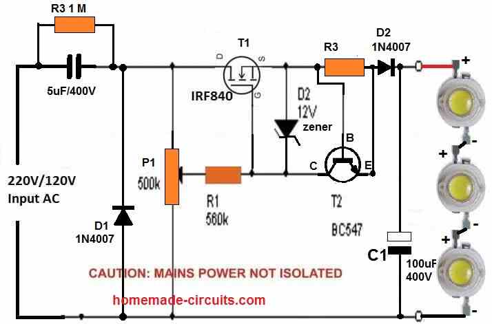 In the above diagram due to the presence a single diode D1 only half AC cycles are delivered across the MOSFET, causing 50% less stress and heat dissipation on the MOSFET.
However, the capacitor C1 parallel to the LED string ensures that the LED keeps getting the required power even during the absence of the other AC half cycles.
You can add more number of LEDs in series, a maximum upto 300 / 3.3 = 90 LEDs.
Make sure to adjust the P1 pot accordingly to adjust the output voltage to match the LED string's max forward voltage.
Likewise.
adjust the base/emitter resistor of T2 (BC547) to match the LED max current spec.
Why use LEDs
⇧LEDs are being Incorporated in vast magnitudes today for everything that may involve lights and illuminations. White LEDs have especially become very popular due to their mini size, dramatic illuminating capabilities and high efficiency with power consumptions. In one of my earlier post I discussed how to make a super simple LED tube light circuit, here the concept is quite similar but the product is a bit different with its specs. Here we are discussing the making of a simple LED bulb CIRCUIT DIAGRAM, By the word "bulb" we mean the shape of the unit and the fitting secs will be similar to that of an ordinary incandescent bulb, but actually the whole body of the "bulb" would involve discrete LEDs fitted in rows over a cylindrical housing. The cylindrical housing ensures proper and equal distribution of the generated illumination across the entire 360 degrees so that the entire premise is equally illuminated. The image below explains how the LEDs needs to be installed over the proposed housing. The circuit of a LED bulb explained here is very easy to build and the circuit is very reliable and long lasting. The reasonably smart surge protection feature included in the circuit ensures an ideal shielding of the unit from all electrical power ON surges.
How the Circuit Functions
⇧The diagram shows a single long series of LEDs connected one behind the other to form a long LED chain. To be precise we see that basically 40 LEDs have been used which are connected in series. Actually for a 220V input, you could probably invorporate around 90 LEDs in series, and for 120V input around 45 would suffice. These figures are obtained by dividing the rectified 310V DC (from 220V AC) by the forward voltage of the LED. Therefore, 310/3.3 = 93 numbers, and for 120V inputs it's calculated as 150/3.3 = 45 numbers. Remember as we go on reducing the number of LEDs below these figures, the risk of switch ON surge increases proportionately, and vice versa. The power supply circuit used for powering this array is derived from a high voltage capacitor, whose reactance value is optimized for stepping down the high current input to a lower current suitable for the circuit. The two resistors and a capacitor at the at the positive supply are positioned for suppressing the initial power ON surge and other fluctuations during voltage fluctuations. In fact the real surge correction is done by C2 introduced after the bridge (in between R2 and R3). All instantaneous voltage surges are effectively sunk by this capacitor, providing a clean and safe voltage to the integrated LEDs at the next stage of the circuit.
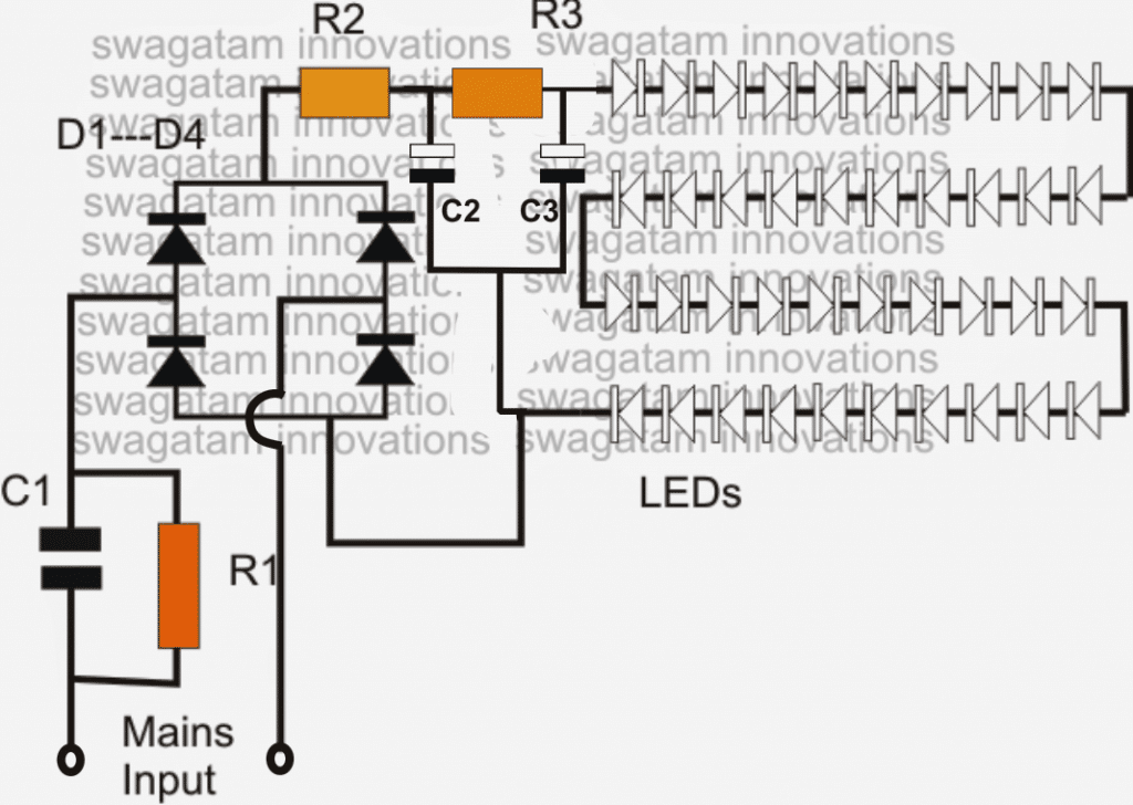
Parts List
R1 = 1M 1/4 watt R2, R3 = 100 Ohms 1watt, C1 = 474/400V or 0.5uF/400V PPC C2, C3 = 4.7uF/250V D1---D4 = 1N4007 All LEDs = white 5mm straw-hat type input = 220/120V mains... The above design lacks a genuine surge protection feature and therefore could be severely prone to damage in the long run....in order to safeguard and guarantee the design against all sorts of surge and transientsThe LEDs in the above discussed LED lamp circuit can be also protected and their life increased by adding a zener diode across the supply lines as shown in the following image. The zener value shown is 310V/2 watt, and is suitable if the LED light includes around 93 to 96V LEDs. For other lower number of LED strings, simply reduce the zener value as per the total forward voltage calculation of the LED string. For example if a 50 LED string is used, multiply 50 with the forward drop of each LED that is 3.3 V which gives 50 x 3.3 = 165V, therefore a 170V zener will keep the LED well protected from any sort of voltage surge or fluctuations....and so on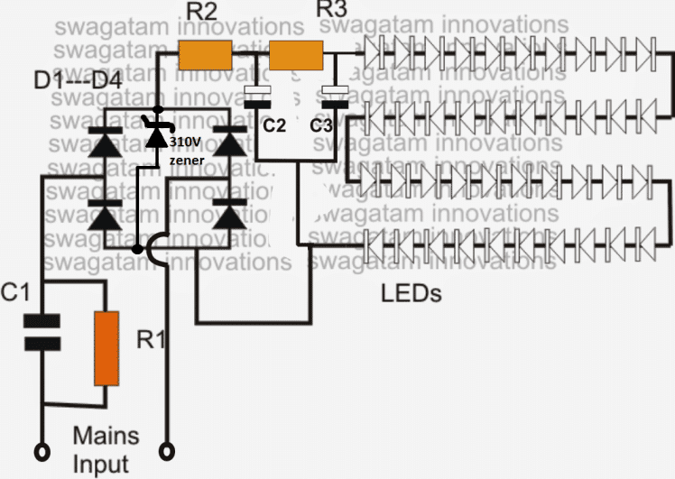 Video clip showing an LED circuit circuit using 108 numbers of LED (two 54 LED series strings connected in parallel)
High Watt LED Bulb using 1 watt LEDs and Capacitor
⇧A simple high power LED bulb can be built using 3 or 4nos 1 watt LEDs in series, although the LEDs would be operated only at their 30% capacity, still the illumination will be amazingly high compared to the ordinary 20mA/5mm LEDs as shown below.
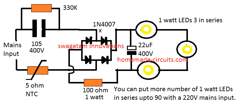 Moreover you won't require a heatsink for the LEDs since these are being operated at only 30% of their actual capacity.
Likewise, by joining 90nos of 1 watt LEDs in the above design you could achieve a 25 watt high bright, highly efficient bulb.
You may think that getting 25 watt from 90 LEDs is "inefficient", but actually it is not.
Because these 90nos of 1 watt LEDs would be running at 70% less current, and therefore at zero stress level, which would allow them to last almost forever.
Next, these would be comfortably working without a heatsink, so the entire design could be configured into a much compact unit.
No heatsink also means minimum effort and time consumed for the construction.
So all these benefits ultimately makes this 25 watt LED more efficient and cost effective than the traditional approach.
Circuit Diagram#2
⇧Surge Controlled Voltage Regulation
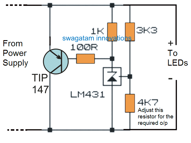
⇧If you require an improved or a confirmed surge control and voltage regulation for the LED bulb, then the following shunt regulator could be applied with the above 3 watt LED design:
Solid State LED Bulb Circuit with Dimmer Control using IC IRS2530D
⇧A simple yet efficient mains transformerless solid state LED controller circuit is explained here using a single full bridge driver IC IRS2530D.
Introduction
⇧Normally LED control circuits are based on buck boost or flyback principles, where the circuit is configured to produce a constant DC for illuminating an LED series. The above LED control systems have their respective drawbacks and the positives in which the range of operating voltage and the number of LEDs at the output decide the efficiency of the circuit. Other factors like whether the LEDs are included in parallel or series or whether they need to bedimmed or not, also affects the above typologies. These considerations make these LED control circuits rather dicey and complicated. The circuit explained here employs a different approach and relies on a resonant mode of application. Though the circuit does not provide direct isolation from the input AC, it has the features of driving many LEDs with current levels as high as 750 mA. The soft switching process involved in the circuit ensures greater efficiency to the unit.
How the LED Controller Functions
⇧Basically the mains transformerless LED control circuit is designed around the fluorescent lamp dimmer control IC IRS2530D. The circuit diagram shows how the IC has been wired up and how its output has been modified for controlling LEDs in place of the usual fluorescent lamp. The usual preheating stage required for a tube light utilized a resonant tank which is now effectively replaced by a LC circuit suitable for driving LEDs. Because the current at the output is an AC, the need of a bridge rectifier at the output became imperative; this makes sure that current is continuously passing through the LEDs during every switching cycle of the frequency. The AC current sensing is done by the resistor RCS, placed across the common and the bottom of the rectifier. This provides an instant AC measurement of the amplitude of the rectified LED current. The DIM pin of the IC receives the above AC measurement via the resistor RFB and capacitor CFB.This allows the dimmer control loop of the IC to keep track of the LED current amplitude and regulates it by instantaneously varying the frequency of the half bridge switching circuit, such that the voltage across the LED maintains a correct RMS value. The dimmer loop also helps to keep the LED current constant irrespective of the line voltage, load current and temperature changes. Whether a single LED is connected or a group in series, the LED parameters is always maintained correctly by the IC.Alternatively the configuration may also be used as a high current transformerless power supply circuit.
Circuit Diagram#3
⇧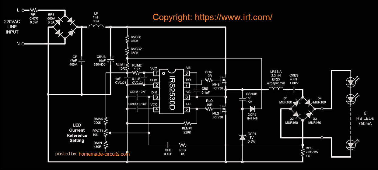 Original article can be foundhere
Getting Started With NodeMCU (ESP8266)
Introduction to NodeMCU (ESP8266)
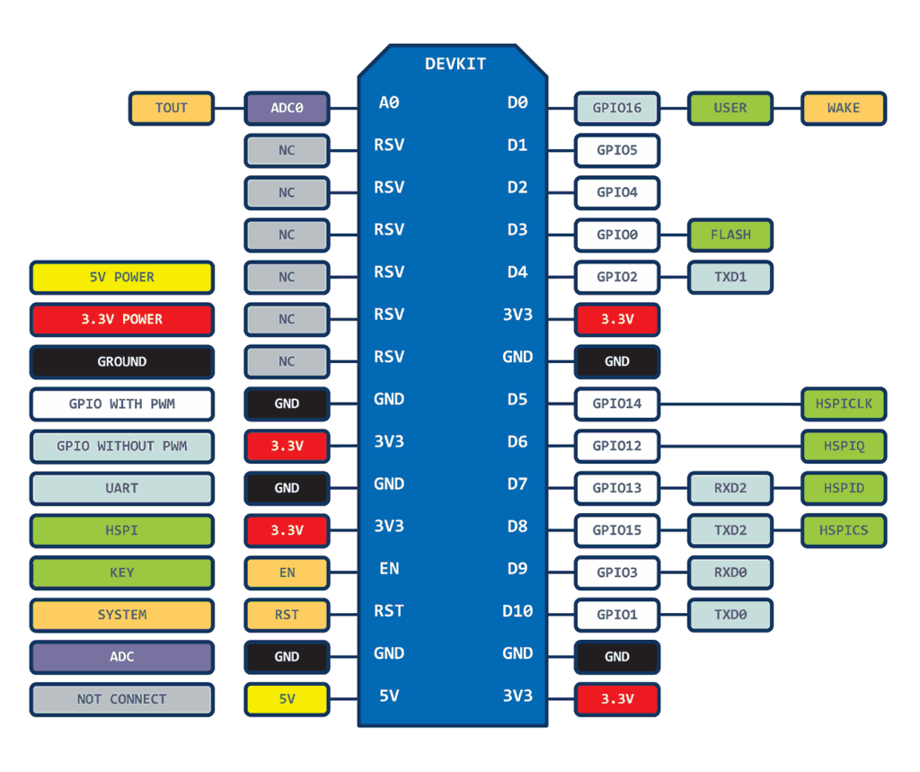 The ESP8266 is a low cost microcontroller with on-board WiFi functionality.
Here are the technical specifications.
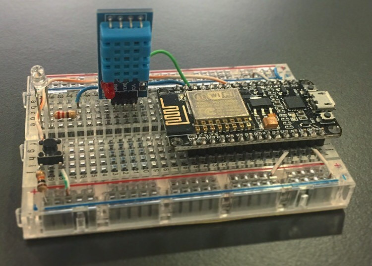
Materials for this Project
Set up the IDE for NodeMCU
First, download and install the Arduino IDE from the Arduino website. You can also use the Learn Robotics Cloud IDE if you'd like the flexibility from programming in the browser!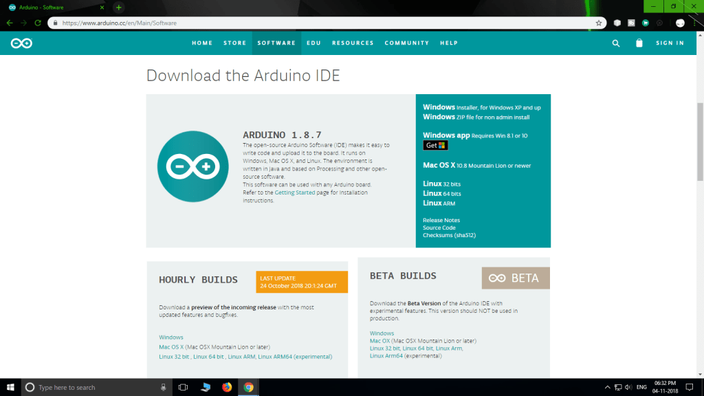 Now to program the ESP development board, the Arduino IDE should have list of boards.
For that we have to install all the ESP boards.
First Goto >> Files >> Preferences >> and paste the following link in '
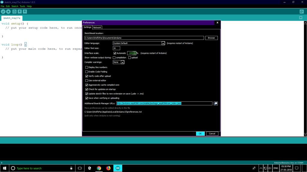 Then, Goto >> Tools >> Board >> Board Manager.
Scroll down to find '
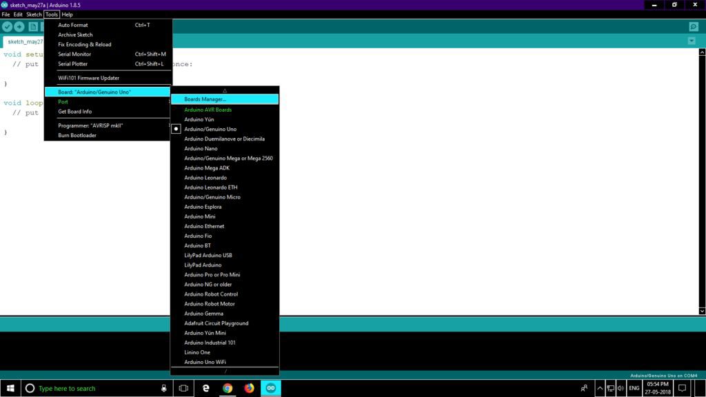
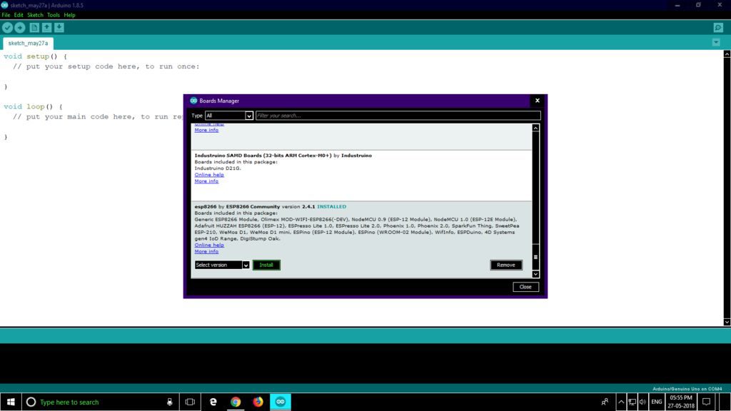 Now to connect the NodeMCU to your PC, you have to install CP210X driver.
Download the latest version compatible to your OS from this website.
Select the right board from the downloaded list.
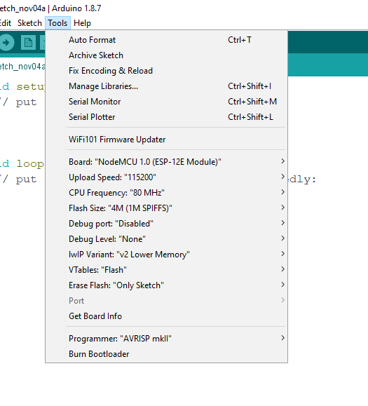
In this article I have used NodeMCU 1.0 (ESP-12E Module), so I will select that.
Goto >> Tools >> Board >> Select the ESP board you have.
After selecting the correct board, keep the settings as follows:
Flash Size : "4M (3M SPIFFS)"
Debug Port : "Disabled"
Debug Level: "None"
IWIP Variant: "V2 Lower Memory"
CPU Frequency: "80Mhz"
Upload Speed: "921600"
Erase Flash: "Sketch On"
Port : "COM port available" (where the device is connected should show up)
Now the board is ready to be programmed.
Upload the Sketch to NodeMCU
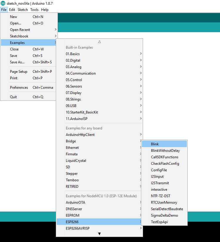 Now that the IDE is setup for NodeMCU you can test it by uploading an Example sketch as follows :-
Files >> Examples >> ESP8266.
Select the Blink example and upload it.
The on board LED should start to blink.
Now the on board LED is connected to Pin D0 of the MCU.
You can connect an external LED to the pin D0.
Now to write sketches for NodeMCU you should know the Pins as NodeMCU have different pin mapping.
You can either use D0...D10 or use the following :-
D0 = 16
D1 = 5
D2 = 4
D3 = 0
D4 = 2
D5 = 14
D6 = 12
D7 = 13
D8 = 15
D9 = 3
D10 = 1
Hope you enjoyed this post and found it informative.
If you have any questions, you can ask them in the comments, below.
Next time we will see how Projects can be controlled over the Internet through your Web Browser.
Getting Started With NodeMCU (ESP8266) Using Arduino IDEIn this article, I will be sharing with you...
how to get started with NodeMCU ESP8266 development board how you can program it easily using good old Arduino IDE and take your project to next level with WiFi connectivity.
Before we get started, I assume that you have a basic knowledge about Arduino and its development
Home automation
Hack a PIR Motion Sensor with an ESP8266 Raspberry Pi Motion Detector with Photo Capture Car Plate Recognition System with Raspberry Pi and Node-RED CCTV Raspberry Pi Based System with Storage using MotionEyeOS Control Sonoff Basic Switch with ESP Easy Firmware and Node-RED Reprogram Sonoff Smart Switch with Web Server Alexa (Echo) with ESP32 and ESP8266 – Voice Controlled Relay ESP8266 Wi-Fi Button – DIY Amazon Dash Button Clone Build a Multisensor Shield for ESP8266 ESP8266 Multisensor Shield with Node-RED Nextion Display with ESP8266 – Touchscreen User Interface for Node-RED ESP8266 Publishing DHT22 Readings to SQLite Database ESP8266 Publishing DHT22 Readings with MQTT to Raspberry Pi ESP8266 – Wireless Weather Station with Data Logging to Excel Raspberry Pi Publishing MQTT Messages to ESP8266 Node-RED with Xiaomi Mijia Bedside Lamp (Wi-Fi and Bluetooth) Node-RED with Xiaomi Yeelight RGBW Smart Bulb Node-RED with WS2812B Addressable RGB LED Strip Node-RED with Raspberry Pi Camera (Take Photos) Video Streaming with Raspberry Pi Camera ESP8266 and Node-RED with MQTT (Publish and Subscribe) Exporting and Backing Up your Node-RED Nodes What is MQTT and How It Works $10 DIY WiFi RGB LED Mood Light with ESP8266 9 Home Automation Open-Source Platforms for Your projects Build a Home Automation System for $100 Control a 12V Lamp via SMS with ArduinoChannel State Information
信道状态信息 是无线通信中描述信道状态的详细数据。 它通过分析 Wi-Fi 信号在不同子载波上传输时的幅度和相位变化,提供了信道的状态信息。 Wi-Fi 信号从路由器传输到 ESP32 人的动作会干扰 Wi-Fi 信号的传播路径,导致信道状态发生变化。 CSI 可以捕捉这些变化,并通过算法分析来推断环境中的活动情况。 当动作检测或者存在检测的计算结果超出了阈值,ESP32 就会判定室内有人在活动。 控制灯光调亮并打开电扇。 当人体停止动作后,动作检测的结果会低于阈值。 但是 CSI 依然可以通过存在检测判断室内是否有人。 ESP32 可以根据结果保持灯光继续点亮,并将风扇切换成更舒适的自然风。 当人离开屋子后,检测算法的结果会低于阈值,从而确认室内无人,并自动关闭家中电器,以达到节省能源的效果。 当一段时间窗口内出现多次计算结果超过阈值的情形,就可以判断环境中发生了动作。 其他应用 Wi-Fi CSI 还可以用于高精度的室内定位。 通过分析多个 Wi-Fi 接入点(AP)或多个终端设备(STA)之间的 CSI 数据,定位算法(如指纹定位、到达角度(AoA)分析等可以计算出人所在的位置。 随着人体移动,CSI 数据会持续变化,定位系统可以通过这些变化实时更新位置,实现动态追踪。 我们还可以让室内的智能家居与 CSI 产生联动。 例如,当走到书桌前,台灯会自动打开; 风扇根据人的位置调整风向。 开发资源 ESP 无感方波ADC方案 ESP32 CSI Introduction and examplesFree Online Circuit Simulators
list of Free Online Circuit Simulators
Tinkercad
Falstad
simulator.io
circuit.io
CircuitCloud
PartSim
Docircuits
EasyEDA
CircuitLab
CircuitSim
EveryCircuit
Tinkercad
Falstad
simulator.io
circuit.io
CircuitCloud
PartSim
Docircuits
EasyEDA
CircuitLab
CircuitSim
EveryCircuit
Online circuit simulators
list of Free Online Circuit Simulators
Tinkercad
Tinkercad Tinkercad is an Autodesk product that allows users to simulate electronic circuits. It comes with a fast simulator and a ton of components. You can edit components as well as connect them using wires. The most interesting feature of Tinkercad is Arduino simulation. You can also export your circuit from Tinkercad as source code to edit using Code blocks or C++.Falstad
Falstad This site contains a lot of educational-based simulators for subjects such as Physics, Math, and Engineering. The site allows you to design and simulate basic electronic circuits. It even animates the direction of the current flow. Here’s is the list of some components present: Resistor Passive components Input and sources Output and labels Active components Digital chips Analog and hybrid chipssimulator.io
Simulator.io This simulator also has a public library where you can browse circuit samples. It also allows you to load and tinker with these designs into your editor. This site has a great simulator that allows you real-time interaction with your tests via the clocks and switches. You will be able to control your simulations clock signal. The site also allows you to add up to 7 friends to collaborate on a project. You will find the following components: Gates Adder Memory Switches and LEDs Advanced Output Code convertercircuit.io
Circuit.io This online simulator is amazing as it has near-realistic electronic components. For example, when using the OR Gate you can see its all inputs and outputs. This gives a clear distinction between the Vcc and the Ground. You can also toggle between the basic and advanced views. It has a majority of the basic components that have been categorized under: Power battery USB Connect Input OutputCircuitCloud
Circuit-Cloud This is another great free online circuit simulator that offers a fairly good public library. The site has an added feature that allows you to specify who you wish to share your circuit designs with. You also have the choice of sharing the designs with the public. A handy feature is that you can make your public work private at any particular moment. The website boasts of having both analog and digital components. Some of the components in these categories include:PartSim
PartSim A great online circuit tool that allows you to carry out both basic and advanced circuit design and simulation. It comes with circuit design templates that will aid you in your design coupled with powerful search functionality. The collection of components is good with the components being arranged in categories ranging from generic parts, vendor parts, electrical and electronic components, electromechanical, and many others.Docircuits
Simulation in DoCircuits It’s a great online circuit simulator for both basic and advanced circuitry. The components are majorly dynamic allowing the user to assign whatever value they wish. It even contains both analog and digital components.EasyEDA
EasyEDA This is easily the best free online circuit with its great features, professional-level components, and user interface. This site also includes a PCB editor. It allows you to control your component functionality. The component library is vast and if the component you desire is not present in the standard library, you can look for them in the user-contributed library.CircuitLab
CircuitLab This site is great for the design and simulation of intermediate circuits. It contains almost all the basic components. You can save your design as a PDF, PNG, or SVG file. You can even carry out time domain and frequency domain analysis on your circuit.CircuitSim
CircuitSim This is a great online circuit simulation that is not only free but also open source. It is one of the first free open-source online circuit simulators. It is great for beginners and students to learn some circuit basics.EveryCircuit
Everycircuit It’s a simple easy-to-use circuit simulator with good quality graphics. The component library has enough components to design basic circuits or for learning purposes.DLP技术核心DMD芯片原理介绍
前段时间国际领先的汽车照明企业马瑞利研发的一款h-Digi车灯模块入围2020年《美国汽车新闻》PACE奖决赛。 h-Digi模块首次采用了包含130万个微镜的芯片。 这里的微镜芯片就是DLP技术,数字光处理技术,数字光处理技术的核心就是DMD芯片。 DLP技术的应用领域很多,比如投影仪、电视、手机、3D打印等,应用的时间也有几年时间了。 但是这项技术被引入到车灯照明领域还是第一次。 所以,对于车灯领域的研发人员可能很多人还不太熟悉。 首先了解一下。
 光电显示
光电显示
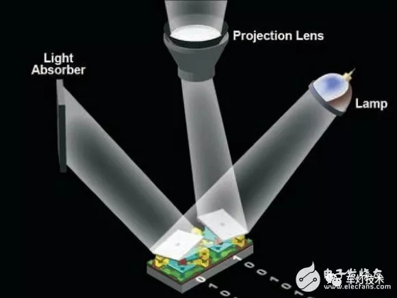 DMD芯片工作原理
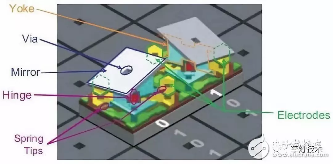 微反射镜结构
在DMD芯片,微反射镜是其最小的工作单位,也是影响其性能的关键。
微反射镜的体积非常小,但是依然拥有不同于液晶的复杂机械结构——每块微反射镜都有独立的支撑架,并围绕铰接斜轴进行+/-12°进行的偏转。
对于微反射镜这种微型机械,传统的机械或是液压控制已无法使用(即使能够使用,也会由于机械磨损而迅速损坏),因此在微反射镜的两角布置了两个电极,通过电压控制控制偏转,获得了高精度的控制能力和无限的偏振寿命。
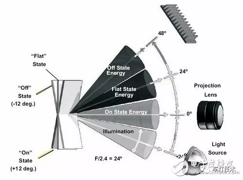
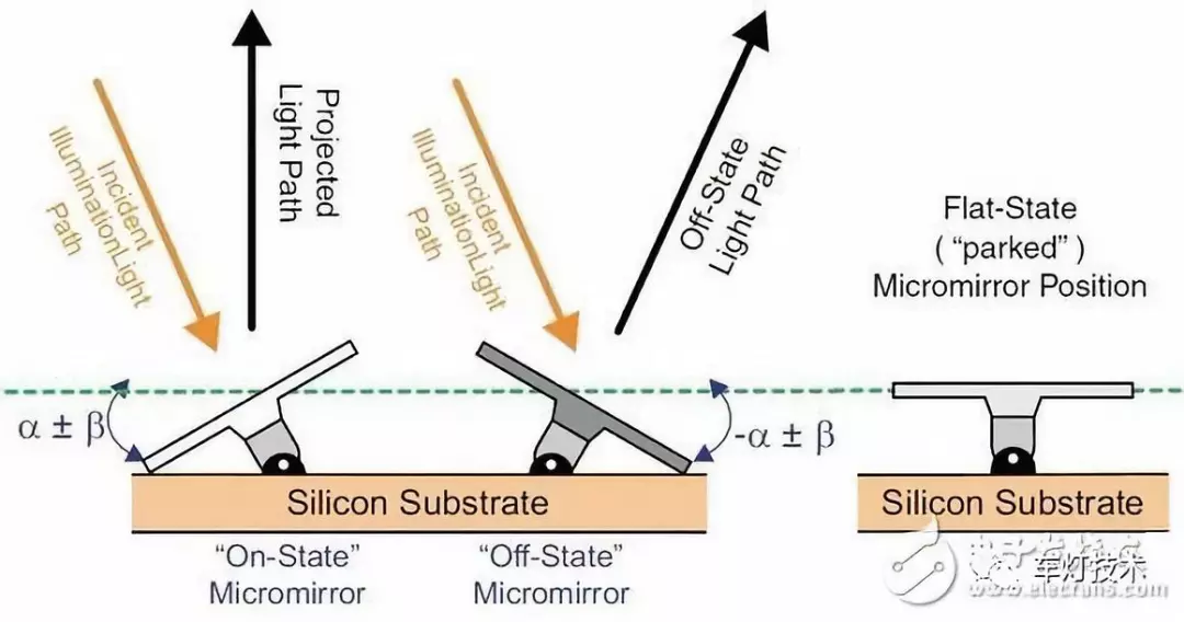
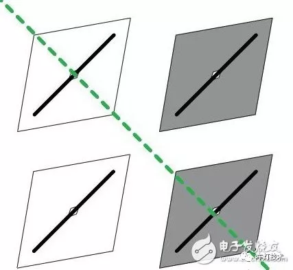
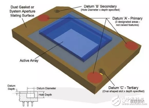
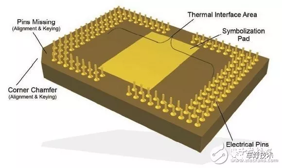
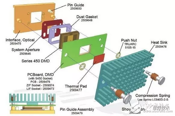
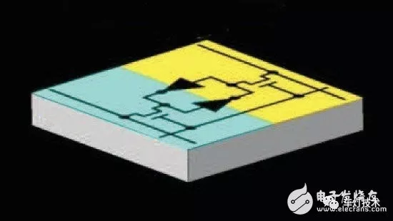
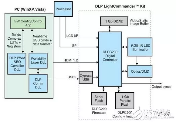
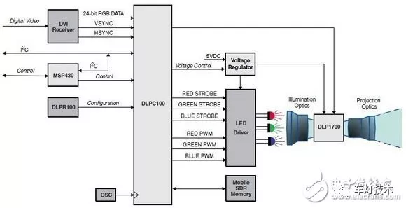
投影仪的DMD芯片
投影仪芯片是投影仪核心部件之一,它的类型决定了投影仪的成像效果和性能。

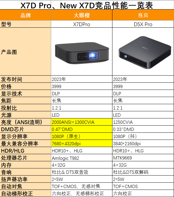 由此可见由于芯片不同,显示分辨率和最大兼容分辨率也拉开了差距。
投影仪的分辨率分为原生分辨率和抖动分辨率,0.47" DMD芯片所对应的是原生1080P分辨率,而0.33" DMD芯片是抖动而来的1080P分辨率,并非原生。
原生分辨率是指投影仪的实际分辨率,也就是它可以显示的最高分辨率。
例如,如果一个投影仪的原生分辨率是1920x1080,那么它能够显示的最高分辨率就是1920x1080。
抖动分辨率是指投影仪可以通过特殊的技术来提高分辨率,但并不是真正的原生分辨率。
例如,一个投影仪的原生分辨率是800x600,但它可以通过抖动技术提高到1024x768的分辨率,这就是抖动分辨率。
一般来说,原生分辨率越高,投影效果越清晰,但价格也越高。
而抖动分辨率虽然能够提高分辨率,但画面可能会产生模糊或者失真等影响视觉效果的问题。
由此可见大眼橙X7DPro的0.47″DMD芯片已然让它成为三千价格段中的最高DMD配置。
挑选投影仪时,务必要认准芯片参数,芯片才是观影体验的最大保障