This custom menu is in part a virtual numpad emulator and a user perspective navigation tool.
Activation
Open Blender and go to Preferences then the Add-ons tab.
Click 3D View then 3D Navigation to enable the script.
Interface
Located in the 3D View ‣ Sidebar ‣ View tab
This add-on is split over two panels.
3D Nav
This panel provides some common navigation tools and emulates the numpad hot keys.
View Global/Local
Switch Global/Local view.
View Persp/Ortho
Switch perspective/orthographic view mode.
View Camera
View from active camera.
Align View from
Front/Back
Align view to front/back.
Left/Right
Align view to left/right.
Top/Bottom
Align view to top/bottom.
Lock View to Object
Select an object to align view, from the list.
View to Select
Align view on selected object.
Cursor
World Origin
Snap cursor to center (scene 0,0,0).
View
Align view to center (scene 0,0,0).
Cursor to Selected
Snap cursor to object center (selected).
Pan Orbit Zoom Roll
This panel provides incremental “User Screen View Perspective” navigation in the Sidebar.
Up
Move towards the top of your screen.
Down
Move towards the bottom of your screen.
Left
Move to the users left or left of screen as you view it.
Right
Move to the users right or right of screen as you view it.
Zoom In/Out
Zoom the view in/out.
Roll Left/Right
Roll the view left/right.
Reference
Category
3D View
Description
Navigate the 3D View and camera from the Sidebar.
Location
3D View ‣ Sidebar ‣ View tab
File
space_view3d_3d_navigation.py
Author
Demohero, uriel, meta-androcto
Maintainer
Brendon Murphy (meta-androcto)
License
GPL
Support Level
Community
Note
This add-on is bundled with Blender.
Math Vis Console
Sometimes when writing Python scripts you stumble on complicated
matrix transformations, ray intersections, rotation conversions, mesh modifications, etc.
where its useful to view lines, points and matrices in the viewport to better understand the problem.
Creating mesh data for this purpose isn’t difficult but is cumbersome.
The purpose of this add-on is to make it as quick and easy as possible.
Activation
Open Blender and go to Preferences then the Add-ons tab.
Click 3D View then Math Vis (Console) to enable the script.
Instructions
Math Vis works by displaying Python Console defined mathutils typed variables in the 3D Viewport.
The following types are supported:
Create a Python Console editor.
In the Python Console define a mathutils variable:
hello_world=Vector((1,2,3))
You should now be able to see this point in the 3D View!
Reference
Category
3D View
Description
Display console defined mathutils variables in the 3D View.
Location
Properties ‣ Scene ‣ Python Console Menu
File
space_view3d_math_vis.py
Author
Campbell Barton
Maintainer
Campbell Barton
License
GPL
Support Level
Official
Note
This add-on is bundled with Blender.
MeasureIt
MeasureIt is an add-on designed for displaying measures in the viewport,
making the process of design objects with exact measures, easier.
These tools are extremely useful for any job that requires exact measurements,
including architectural projects, technical design and 3D printing.
Activation
Open Blender and go to Preferences then the Add-ons tab.
Click 3D View then MeasureIt to enable the script.
Interface
Overview
Located in the 3D View ‣ Sidebar ‣ View tab
The MeasureIt Tools panel is described below.
To view the measures you need to press the Show button.
Many measure styles appear grayed out in the menu, these are active in Edit Mode.
The Mesh Debug sub panel has extra display options.
The Items sub panel appears after adding a measure. This contains the color settings for each measure.
The Configuration sub panel contains the font settings.
The Render sub panel contains the render settings.
Usage
Mesh vertex to vertex measure: Length between vertices in the same mesh.
Mesh vertex labeling: Add a label to any mesh vertex.
This allows identify easily different areas or objects in the scene.
Object to object: Distance between object origins, vertex to origin or vertex to vertex.
Object to origin: Distance between object origin to scene origin or vertex to scene origin.
Allows work with different scales.
The measures can be used with meshes, empties, lights, and cameras.
As all measure definitions are saved in the blend-file, you can save the file and
the next time you use it, the measures will be ready.
Reference
Category
3D View
Description
Tools for measuring objects in the 3D View.
Location
3D View ‣ Sidebar ‣ View tab
File
measureit folder
Author
Antonio Vazquez (antonioya)
Maintainer
Antonio Vazquez (antonioya)
License
GPL
Support Level
Community
Note
This add-on is bundled with Blender.
Stored Views
Stored Views has three modes of operation, depending on which the following are saved or restored.
Save stored views to your blend-file to easily have access to saved views later.
Activation
Open Blender and go to Preferences then the Add-ons tab.
Click 3D View then Stored Views to enable the script.
Interface
Located in the 3D View ‣ Sidebar ‣ View tab.
View
Save multiple view locations for easy navigation between views.
POV
Save Point of View –> Perspective and Local modes.
Camera to View
Move the selected camera to current view.
New Camera to View
Create a new camera to current view.
Save Current
Save the View or POV.
Camera Selector
Tools for camera selection and management.
Camera
Make the camera active.
Preview Camera
Make the camera active, selected and Camera to View in one button.
Add Camera Marker
Add a camera marker to help animating between cameras.
Instructions
First Activate the user interface and storage by pressing Initialize.
With the View button active, Zoom, move or rotate the camera into a position you like.
(Useful setting up camera locations and modeling specific areas of a mesh.)
Or with the POV button active, change the user perspective or local views.
Press Save Current to create a list of each stored view or point of view.
You can move selected camera or create a new camera to the stored view.
(Useful for setting up camera shots to different views.)
The camera selector works in a similar way. Each camera is listed and
you can make a camera active by pressing the camera icon.
You can view each camera pressing the screen icon and also add camera markers using the arrow icon.
(Useful for setting up camera switching during animations.)
As all stored definitions are saved in the blend-file, you can save the file and
the next time you use it, the stored views or point of view will be ready.
Reference
Category
3D View
Description
Save and restore user defined views, POV and camera locations.
Location
3D View ‣ Sidebar ‣ View tab
File
space_view3d_stored_views.py
Author
nfloyd, Francesco Siddi
Maintainer
Brendon Murphy (meta-androcto)
Contributors
ramboblender
License
GPL
Support Level
Community
Note
This add-on is bundled with Blender.
Assign Shape Keys
This add-on lets you assign one or more Bézier curve(s) as shape keys to other curve.
Useful for morphing curves and curve based text objects.
Activation
Open Blender and go to Preferences then the Add-ons tab.
Click Add Curve then Assign Shape Keys to enable the script.
Interface
Located in the 3D View ‣ Sidebar ‣ Edit tab.
Usage
Select the target and shape key Bézier curve objects.
Make sure the target is the active object; you can do this by
Shift-RMB-clicking the target curve after the other selections are made.
Go to the Curve Shape Keys tab and click Assign Shape Keys button.
Now a copy of the active object curve will be created, which will have the other selected curves as its target.
If the Remove Shape Key Objects option is checked, the selected curve objects will be deleted
and only the target is kept.
There are some options to align the closed (cyclic spline) target and the shape-key curves.
Also it’s possible to match individual parts from a multipart (multiple splines) of target
and shape key curves (e.g. a text object converted into a curve) based on various criteria.
For smoother transition, you can subdivide the segments of one of the curves in the selection group.
Manual Alignment of Starting Vertices
In Edit Mode the Assign Shape Keys panel shows a single button – Mark Starting Vertices.
When clicked, all the starting vertices of the closed splines (disconnected parts) of
the selected curves are indicated by a marking point. Now if you select any vertex,
the marker moves to this selected vertex, indicating the new starting vertex.
You need to confirm the new positions by pressing Return.
Pressing Esc, reverts the positions to the earlier order.
Reference
Category
Add Curve
Description
Assigns one or more Bézier curves as a shape key for another Bézier curve.
Location
Sidebar ‣ Edit tab
File
curve_assign_shapekey.py
Author
Shrinivas Kulkarni
Maintainer
Shrinivas Kulkarni
License
GPL
Support Level
Community
Note
This add-on is bundled with Blender.
BTracer
The purpose of this script is to add tools that are similar to C4D Tracer.
Btrace provides several ways to trace objects and particles and animate the resulting curve.
Activation
Open Blender and go to Preferences then the Add-ons tab.
Click Add Curve then BTracer to enable the script.
Interface
Located in the 3D View ‣ Sidebar ‣ Edit tab.
The default setting in the interface is Choose Tool, here you pick what trace methods and functions.
Information
The five main tools (Object Trace, Object Connect, Mesh Follow, Particle Trace, Particle Connect)
all share common settings for the most part. Each tool creates a curve as the end result.
The settings for the curve created can be setup under the Curves Settings button.
The tools have access to a few other features. All of them have access to
the grow curve animation tool which animates the curve radius.
As well as the Color Blender tool.
Object Trace
Creates a curve by joining points of a mesh in a continuous manner or by all edges.
Options to modulate the curves radius or add distortion to mesh before converting.
Objects Connect
Join selected objects with a curve and add hooks to each node.
Particle Trace
Creates a curve from each particle of a system. Keeping particle amount under 250 will make this run faster.
Particle Connect
Connects each particle of a system with a continuous curve.
Mesh Follow
Creates curve from animated mesh object. Following the path of
either the vertices, edges or faces, and also the option to follow the object’s origin.
Grow Curve Animation
Animate the radius of a curve over time. Can be run alone on a curve object, or run with the tools above.
F-Curve Noise
Quick link to add an F-curve modifier to an object.
Color Blender
Assign colors, create color palettes and randomize colors.
Each script has a number of different options which can be used to create some very interesting effects.
Reference
Category
Add Curve
Description
Tools for converting/animating objects/particles into curves.
Location
Sidebar ‣ Create tab
File
btrace folder
Author
liero, crazycourier
Contributors
Atom, MacKracken, meta-androcto
Maintainer
Brendon Murphy (meta-androcto)
License
GPL
Support Level
Community
Note
This add-on is bundled with Blender.
Curve Tools
This add-on provides an extensive set of tools for the manipulating
and editing of curves. Several CAD style curve tools are included.
Activation
Open Blender and go to Preferences then the Add-ons tab.
Click Add Curve then Curve Tools to enable the script.
Interface
Located in the 3D View ‣ Sidebar ‣ Edit tab.
This add-on is split into sub panels with each panel having it’s own specific set of tools.
One Curve
Curve Info
Print splines, segments and empty splines information to the Info header and Info editor.
Calculate Length
Calculate the length of the curve and show in the add-on’s panel.
Curve Splines Info
Print splines information to the Info header and Info editor.
Curve Segments Info
Print segments information to the Info header and Info editor.
Set Origin to Spline Start
Move the origin of the curve to the first point.
Curve
Intersect Curves
Create an intersection between flat curves on the same plane.
Two Curves Loft
Loft
Loft a mesh object between two Bézier curves.
Auto Loft
Turn on to store the loft data if you move or edit the curves.
Update Auto Loft
Press this button to update the new loft mesh position after moving or editing parent curves.
Advanced
Curve Outline
Create an outline around a selected curve object.
Separate Outline or Selected
Separate the Outline mesh from the original.
Fillet
Round or chamfer Bézier point fillets.
Handle Projection
To do.
Divide
Subdivide selection or filleted corners.
Scale Reset
Reset the objects scale to (1, 1, 1).
Birail
It creates a surface from a profile and two paths.
The order in which you select the curves and its direction is important to make this work right.
Convert Selected Faces to Bézier
Select faces and convert them to Bézier curves.
Convert Bézier to Surface
Convert the selected curve to a NURBS surface.
Extended
Offset Curve
Create an offsetted array.
Boolean Two Selected Spline
Boolean selected curves on a 2D plane.
Multi Subdivide
Subdivide with level of details.
Split by Selected Points
Cuts the selected points creating openings.
Remove Doubles
Remove doubled points.
Discretize Curve
Disconnect the selected points.
Array Selected Spline
Create an array of the selected curves in Edit Mode.
Curves Utils
Show Point Resolution
Display the resolution in the interface with a colored overlay.
Show and Arrange Sequence
Display and arrange the sequence.
Remove Splines
Remove selected splines based on a threshold.
Join Splines
Join selected splines based on a threshold.
Pathfinder
Tools for paths.
Reference
Category
Add Curve
Description
Adds functionality for Bézier/NURBS curve/surface modeling.
Location
Sidebar ‣ Edit tab
File
curve_tools folder
Authors
MacKracken, cwolf3d, Alexander Meißner (Lichtso)
Contributors
guy lateur, Alexander Meißner (Lichtso), Dealga McArdle (zeffii), Marvin K. Breuer (MKB)
Maintainer
Vladimir Spivak (cwolf3d)
License
GPL
Support Level
Community
Note
This add-on is bundled with Blender.
Add Curve Extra Objects
This add-on groups many curve object creation add-ons into a single one.
Activation
Open Blender and go to Preferences then the Add-ons tab.
Click Add Curve then Extra Objects to enable the script.
Interface
Located in the 3D View ‣ Sidebar ‣ Create tab.
Located in the 3D View ‣ Add ‣ Curve menu.
Information
Included curve object add-ons:
Curve Profiles (Curveaceous Galore) by Jimmy Hazevoet, testscreenings
Arc, Arrow, Cogwheel, Cycloid, Flower, Helix, Noise, N-sided, Profile, Rectangle, Splat and Star types.
SpiroFit, BounceSpline and Catenary by Antonio Osprite, Liero, Atom, Jimmy Hazevoet
Spiral fit curve to mesh, Bounce Spline inside a mesh, Catenary curve between two mesh objects.
Torus Knots, by Marius Giurgi (DolphinDream), testscreenings
Adds many types of (torus) knots including ten presets.
Bevel/Taper Curve, by Cmomoney
Adds bevel and/or taper curve to active curve.
Surface Objects, by Folkert de Vries
Adds a NURBS surface Plane, Cone, Star, Wedge.
Reference
Category
Add Curve
Description
Add multiple extra curve object types.
Location
3D View ‣ Add ‣ Curve
File
add_curve_extra_objects folder
Author
Multiple Authors
Maintainer
Vladimir Spivak (cwolf3d)
License
GPL
Support Level
Community
Note
This add-on is bundled with Blender.
Ivy Gen
Based on the wonderful code by Thomas Luft and
his original IvyGen program.
Original Blender port by testscreenings, further advances by PKHG and TrumanBlending.
Activation
Open Blender and go to Preferences then the Add-ons tab.
Click Add Curve then Ivy Gen to enable the script.
Interface
Located in the 3D View ‣ Sidebar ‣ Create tab.
Located in the 3D View ‣ Operator.
The Update Ivy operator is separate from the main menu and appears in the 3D View.
You can adjust settings in the panel and press the Update button to update parameters.
Instructions
Select the object you want to grow ivy on.
Enter Edit Mode and select a vertex that you want the ivy to spawn from.
Snap the cursor to the selected vertex.
Enter Object Mode and with the object selected:
Sidebar ‣ Create ‣ Ivy Generator panel adjust settings and choose Add New Ivy.
The Add Default Ivy operator will use the default parameters during creation.
This will generate your initial Ivy Curve and Leaves.
From here you can access the Ivy menu in the Sidebar.
I suggest to make small changes and then press Update Ivy in the 3D View operator.
Reference
Category
Add Curve
Description
Todo.
Location
Sidebar ‣ Create tab
File
add_curve_ivygen.py
Author
testscreenings, PKHG, TrumanBlending
Maintainer
Vladimir Spivak (cwolf3d)
License
GPL
Support Level
Community
Note
This add-on is bundled with Blender.
Sapling Tree Gen
This add-on creates trees. There are many preset tree types to choose from or create your own.
The method is presented by Jason Weber & Joseph Penn in their paper “Creation and Rendering of Realistic Trees”.
Activation
Open Blender and go to Preferences then the Add-ons tab.
Click Add Curve then Sapling Tree Gen to enable the script.
Interface
Located in the 3D View ‣ Add ‣ Curve menu.
Instructions
Once the tree is created there are eight settings to build your tree.
When creating your tree it’s often best to use the settings in order until your familiar with them.
Geometry
Bevel
This determines whether the curve should be shown with its full thickness or only the underlying curve.
Disabled by default to permit rapid feedback on parameter changes.
Bevel Resolution
Determines how smooth the outline of the bevelled curve is.
The lower this value, the smaller the number of vertices but
the resulting geometry will be coarser.
Curve Resolution
Changes the smoothness of the curve along its length. This is only relevant if Handle Type is set to Auto.
Handle Type
Determines the method of interpolation of the curve between Bézier points.
Vector type results in fewer vertices but straight segments.
Auto type smooths the segments but requires more expensive geometry.
Shape
Governs the distribution of branches in order to effect the overall shape of the tree.
Custom Shape
Customize the branch shape along the branch length.
Secondary Splits
Change the style of secondary branches.
Branch Distribution
Adjust branch distribution towards the top or bottom of the tree.
Branch Rings
Grow the Branches in Rings.
Random Seed
Sets the basis on which all random values for the tree are generated.
This can be changed to allow different trees with the same basic parameters to be generated.
Tree Scale
The underlying size of the tree in Blender units.
Scale Variation
The maximum amount that the scale of the tree can vary (up or down) from the value of Scale.
Radius Scale
The scale of the radius at the base of the tree.
Radius Variation
The maximum amount that the radius scale of the tree can vary (up or down) from the value of Radius Scale.
Preset Name
The name of the preset to be exported. This will export all current properties of the tree to
the Sapling preset folder as a py-file.
Export Preset
Export all current properties.
Load Preset
Any presets found in the Sapling preset directory may be imported when selected here.
Limit Import
This can be used to restrict what geometry is created when a preset is imported.
If selected, only two levels of branches and no leaves will be generated.
Branch splitting
There are many variables to explore with branch splitting.
Branch Radius
This sub menu contains the settings for the branch radius.
You can adjust the bevel and taper of the branches here.
Branch Splitting
This sub menu contains the settings for branch splitting.
You can adjust how the branches form and split here.
Settings include levels, height and angle of the split.
Branch Growth
This sub menu contains the settings for branch growth.
You can adjust how the branches grow here.
Settings include length, angle and curvature.
Pruning
This sub menu contains the settings for pruning the branches.
Press the Prune checkbox and you will see the prune object next to the tree.
Change the settings to adjust the prune objects shape to form your tree.
Leaves
This sub menu contains the settings for leaves.
Press the Show Leaves checkbox and you will see leaves on the tree.
Press the Make mesh checkbox if you want to convert the curve to a mesh.
Settings include shape, object type, rotations and scale.
Armature
This sub menu contains the settings to add an armature to your tree.
It’s not recommended to use this function on highly complex trees as it may take time to compute.
Turn of leaves and prune if you have them on.
Press the Use Armature checkbox to add the armature to the tree.
Adjust the armature levels and bone length to your liking.
Do not pose the bones until you have finished the tree.
you are now ready to use the next sub menu Animation.
Animation
This sub menu contains the settings to animate your tree.
It’s recommended to finalize all your settings now.
You will need to have an armature already created above.
Press the Armature Animation checkbox to add the animation to the tree.
Press the Leaf Animation checkbox to add the animation to the leaves if you have them.
Press the Fast Preview checkbox to hide the leaves and bevel for fast animation playback in the viewport.
Settings include speed, wind strength and leaf animation.
Reference
Category
Add Curve
Description
Adds a parametric tree.
Location
3D View ‣ Add ‣ Curve ‣ Sapling Tree Gen
File
add_curve_sapling folder
Author
Andrew Hale (TrumanBlending), Aaron Butcher, CansecoGPC
Maintainer
To Do
License
GPL
Support Level
Community
Note
This add-on is bundled with Blender.
Simplify Curves
The Simplify Curves tool works on a single selected curve object.
It generates a new curve based on the original one.
The higher the Distance Error threshold is set the more control points are removed.
The Simplify F-Curves tool works the same way, but on selected F-curves.
Merge by Distance tool glues nearby points on a single Bézier curve.
In fact it is an analogue of the usual Remove Doubles on a mesh, but for curves.
Unlike the mesh one, it does not connect the points from different parts of the curves,
even if they are on the ends of the two curves.
To glue such points, you must first connect them with Make Segment.
Activation
Open Blender and go to Preferences then the Add-ons tab.
Click Add Curve then Simplify Curves to enable the script.
Interface
The Merge By Distance and Curve Simplify buttons are located in
the 3D View ‣ Curve Context Menu in curve Edit Mode.
The Simplify F-Curves buttons are located in
the Dope Sheet ‣ Action ‣ Graph Editors ‣ Channel menu.
Reference
Category
Add Curve
Description
Simplify curves in the 3D View, and Dope Sheet, merge by distance in 3D View.
Location
3D View ‣ Add ‣ Curve ‣ Curve Simplify,
Dope Sheet and Graph editors ‣ Channel ‣ Simplify F-Curves
File
curve_simplify.py
Author
testscreenings, Michael Soluyanov
Maintainer
To Do
License
GPL
Support Level
Community
Note
This add-on is bundled with Blender.
ANT Landscape
This add-on creates landscapes and planets using various noise types. A.N.T. stands for Another Noise Tool.
Activation
Open Blender and go to Preferences then the Add-ons tab.
Click Add Mesh then A.N.T. Landscape to enable the script.
Interface
Located in the 3D View ‣ Add ‣ Mesh menu.
Located in the 3D View ‣ Sidebar ‣ Create tab.
Instructions
After creating your landscape mesh there’s three main areas in
the Adjust Last Operation panel to design your mesh.
Main Settings: Object and mesh related settings like size and subdivisions.
Noise Settings: Noise related settings that give shape to your terrain.
Displace Settings: Settings for terrain height and edge falloff.
Landscape Panel
Landscape
Landscape will create the mesh and add several panels and tools to the Sidebar.
Landscape Tools
Mesh Displace
Displace selected mesh vertices along normal or X, Y, Z direction.
Weight From Slope
Generates a weighted vertex group slope map based on the Z normal value.
Landscape Eroder
Apply various kinds of erosion to an A.N.T. Landscape grid,
also available in the Weights menu in Weight Paint Mode.
Landscape Main
Here we can adjust the main settings and regenerate the mesh.
Smooth the mesh, Triangulate the mesh, Rename and add materials that you have in your blend-file.
Landscape Noise
Here we can adjust the noise settings and refresh only those settings.
There are many settings and noise types here which allow you to customize your landscape.
Landscape Displace
Here we can adjust the displacement settings and refresh only those settings.
Adjust Height, Falloff and Strata in this section.
Usage
To Do
Reference
Category
Add Mesh
Description
Another Noise Tool: Landscape, erosion and displace.
Location
Sidebar ‣ Create tab
File
ant_landscape folder
Author
Jimmy Hazevoet
Maintainer
To Do
License
GPL
Support Level
Community
Note
This add-on is bundled with Blender.
Archimesh
This tool is specially designed to generate architecture elements, like:
Rooms
Doors
Windows
Kitchen cabinets
Shelves
Columns stairs
Tile roofs
Books
Lamps
Venetian blinds
Roller curtain
Japanese curtains
The original video documentation can be found here:
Video Playlist.
Note that the videos were created for Blender 2.7 series but are still a valid resource.
Activation
Open Blender and go to Preferences then the Add-ons tab.
Click Add Mesh then Archimesh to enable the script.
Interface
Located in the 3D View ‣ Sidebar ‣ Create tab.
Reference
Category
Add Mesh
Description
Generate rooms, doors, windows and architecture objects.
Location
Sidebar ‣ Create tab
File
archimesh folder
Author
Antonio Vazquez (antonioya)
Maintainer
Antonio Vazquez (antonioya)
License
GPL
Support Level
Community
Note
This add-on is bundled with Blender.
Archipack
This add-on features architectural objects and tools.
An extended version is available from the authors Github
as well as the documentation.
Activation
Open Blender and go to Preferences then the Add-ons tab.
Click Add Mesh then Archipack to enable the script.
Interface
Located in the 3D View ‣ Sidebar ‣ Create tab.
Reference
Category
Add Mesh
Description
Architectural object creation.
Location
Sidebar ‣ Create tab
File
archimesh folder
Author
s-leger
Maintainer
s-leger
License
GPL
Support Level
Community
Note
This add-on is bundled with Blender.
BlenderKit
Online Blenderkit Library, materials, models, brushes and more.
An extended version is available from the authors site
as well as the documentation.
Activation
Open Blender and go to Preferences then the Add-ons tab.
Click Add Mesh then BlenderKit Asset Library to enable the script.
Reference
Category
Add Mesh
Description
Online Blenderkit Library, materials, models, brushes and more.
Location
3D View ‣ Sidebar ‣ Blenderkit
File
blenderkit folder
Author
Vilem Duha, Petr Dlouhy
Maintainer
Vilem Duha
License
GPL
Support Level
Community
Note
This add-on is bundled with Blender.
Bolt Factory
This add-on creates bolts and nuts with options for bolt/nut, bit type and head type.
Activation
Open Blender and go to Preferences then the Add-ons tab.
Click Add Mesh then BoltFactory to enable the script.
Interface
Located in the 3D View ‣ Add ‣ Mesh menu.
Usage
To Do
Reference
Category
Add Mesh
Description
Add a bolt or nut.
Location
3D View ‣ Add ‣ Bolt
File
add_mesh_BoltFactory folder
Author
Aaron Keith
Maintainer
To Do
License
GPL
Support Level
Community
Note
This add-on is bundled with Blender.
Discombobulator
This add-on creates a greeble object based on selected faces.
It quickly creates science fiction style panels across your mesh.
Activation
Open Blender and go to Preferences then the Add-ons tab.
Click Add Mesh then Discombobulator to enable the script.
Interface
Located in the 3D View ‣ Add ‣ Mesh menu.
Discombobulator works in mesh Object Mode and mesh Edit Mode.
Instructions
Select the quad faces you want to add greebles to.
3D View ‣ Add ‣ Mesh ‣ Discombobulator.
Now you will see the interface but nothing happens to the mesh.
It’s useful at this point to read the Usage Information at the top of the panel.
With the default settings press OK and you will see a new mesh object created that has raised areas.
Let’s look at the settings below.
Protrusions Settings
Make Protrusions
This checkbox turns on the functions for protrusions.
If you turn it off, nothing will happen when you run the script.
You may want to turn Protrusions off if you are using only the Doodads function described further below.
Min/Max Height
Adjust the height of the protrusions, you can use negative and positive values.
The negative values will create the protrusions on the opposite side of the selected face(s).
Min/Max Taper
Adjust the taper of the protrusions. This will affect the pointiness of the protrusions.
1, 2, 3, 4
These checkboxes provide options for the subdivision of the faces or the amount of protrusions per face.
Based on random, if you have all selected, each face will have either 1, 2, 3 or 4 protrusions.
Use only one or any combination and the faces will only have your selected value(s).
Repeat Protrusions
This button creates extra levels of protrusions built on top of the first set of protrusions.
It’s important not to set this too high as it may take time to compute.
Note also that repeating protrusions is based on face normals and
will create protrusions on all faces created in the previous iteration.
Doodads Settings
This checkbox allows you to use your own mesh object and have it applied on top of the protrusions.
Doodads can be a little tricky to set up:
Select the object(s) you want to use as a doodad.
Run Discombobulator and press Pick Doodad.
Select your mesh to scatter doodads on and run Discombobulator.
Materials Settings
These settings allow you to add materials to the sides and tops of the protrusions.
It’s best to set up your materials first. Add two different materials to your mesh (two materials slots).
Number 0 will be the first slot in your materials, number 1 will be the second slot.
Run Discombobulator and you can pick the material for the top or sides.
Reference
Category
Add Mesh
Description
Add Greeble type effect to a mesh.
Location
3D View ‣ Add ‣ Mesh
File
add_mesh_discombobulator folder
Author
Evan J. Rosky (syrux)
Maintainer
To Do
License
GPL
Support Level
Community
Note
This add-on is bundled with Blender.
Geodesic Domes
Original introduction from Andy Houston (Blender 2.4 series)
Geodesic spheres based on icosahedrons, octahedrons and tetrahedrons.
Triangular, hexagonal and hex/tri combo face options.
A function that turns the current shape into its geometric dual (sort of).
Grid, Cylinder, Parabola, Torus and Ball primitives.
Hubs and Struts. Fill out those edges and vertices with your custom, decorative meshes.
Superformula deforming. Create rounded triangles, wobbly shapes, etc.
Introduction by Brendon Murphy (Blender 2.6/7 series)
This script can be used to create geodesic objects, not limited to domes or spheres.
Each mesh type created has it’s own set of editable parameters.
By editing the parameters, you can create many simple or complex mesh shapes.
Create an equal-sided pyramid, a soccer ball, a wine glass and more.
Limited only by your imagination (and some cool math limitations).
Create complex mesh deformations with the superformula parameters.
In the next section we will cover the menu types and how to use the parameters to “design” your mesh.
Activation
Open Blender and go to Preferences then the Add-ons tab.
Click Add Mesh then Geodesic Domes to enable the script.
Instructions
Main
The Main menu is where you will do most of your work.
The geodesic default triangle will be shown in the 3D View and the Object Creation parameters can be accessed here.
Please note: I find it’s easier to use the Object Creation parameters first before moving on to
Faces, Struts and Hubs, these will be explained in the sections below.
For now, let’s look at the Object Types and their parameters:
Objects
There are six Object types you can create by default.
Using the parameters you can build upon these objects to create more object types.
Object Types have unique parameter sets and share the Superformula parameters (described below).
Geodesic Object Class Types
Geodesic
Please note, the Frequency parameters have a high impact on object creation.
To create a Geodesic Dome you must increase the Frequency or the default Triangle.
Subdivide Basic/Triacon
Class 1 is the “equilateral triangle”.
Class 2 is the “cube”.
Hedron
Choose between Tetrahedron, Octahedron, Icosahedron.
Point
Point (vertex), edge or face pointing upwards.
Shape
Choose between tri, hex or star face types.
Round
Choose between spherical or flat. (May not work for all object types.)
Geodesic Object Parameters
Frequency
Subdivide base triangles.
Radius
Overall radius.
Eccentricity
Scaling on the X/Y axis.
Squish
Scaling on the Z axis.
Square (X/Y)
Superellipse action in X/Y.
Square (Z)
Superellipse action in Z.
Rotate (X/Y)
Rotate superellipse action in X/Y.
Rotate (Z)
Rotate superellipse action in Z.
Dual
Faces become vertices, vertices become faces, edges flip.
Geodesic Object Types
There are six Object types you can create.
Each type has it’s own set of parameters.
As you can see most menu items are self explanatory.
The tooltips will give you further information on individual parameters.
Gap
Shrink faces in direction.
Add or remove rows of faces based on height (Z) or (X/Y).
Phase
Rotate around a pivot.
Useful for rotating deformation or use with Gap.
Import Your Mesh
You can import your own mesh into Geodesic Domes for use within the script.
This is limited to the Faces, Struts and Hubs menu’s.
Faces
This Section adds extrusions and edits face structures on a mesh.
Struts
This section allows you to extrude an object along the edges of a mesh.
Hubs
This section allows you to place an object at the vertex on a mesh.
Superformula Menu
The superformula settings add a variety of settings such as pinching, twisting, inflate and
more complex edit types.
Reference
Category
Add Mesh
Description
Create Geodesic object types.
Location
3D View ‣ Add ‣ Mesh
File
add_mesh_geodesic_domes folder
Author
Andy Housten
Maintainer
To Do
License
GPL
Support Level
Community
Note
This add-on is bundled with Blender.
Add Mesh Extra Objects
This add-on groups many mesh object creation add-ons into a single one.
Activation
Open Blender and go to Preferences then the Add-ons tab.
Click Add Mesh then Extra Objects to enable the script.
Interface
Located in the 3D View ‣ Add ‣ Mesh menu.
Information
Included mesh object add-ons:
Parent to Empty by Liero
Parent the selected mesh to an empty object type.
3D Function Surface by Buerbaum Martin (Pontiac), Elod Csirmaz
Create objects with XYZ math functions. Includes several presets by elfnor.
Beam Builder by revolt_randy, Jambay
Create five types of beams.
Gears by Michel J. Anders (varkenvarken)
Create gear and worm type mesh.
Gemstones by Pontiac, Fourmadmen, Dreampainter, Dominic Kroper, (dommetysk)
Create three types of diamond shapes.
Honeycomb by Kayo Phoenix
Create a honeycomb patterned mesh.
Menger Sponge by sugiany
Create iterated Menger sponges.
Pipe Joints by Buerbaum Martin (Pontiac)
Create angled and crossed pipes.
Step Pyramid by Phil Cote (cotejrp1)
Create a step pyramid with variable settings.
Round Cube by Alain Ducharme (phymec)
Create a quad mesh sphere with several presets.
Regular Solid by DreamPainter
Create polyhedron based objects.
Star by Fourmadmen
Create a simple star shape.
Supertoroid by DreamPainter
Create a torus object with new parameters for boxed shape and more.
Teapot by Anthony D’Agostino
Traditional style mesh teapot and a secondary spoon object.
Torus Knot by Anthony D’Agostino
A simple mesh torus knot with three types.
Triangles by Sjaak-de-Draak
Create math based triangles.
Twisted Torus by Paulo_Gomes
Standard torus object with a variable twisted mesh.
Add Vertex by meta-androcto, Pablo Vazquez, Liero, Richard Wilks
Add a single vertex object or object origin as a fast start to mesh editing.
Wall Factory by dudecon, jambay
Add castle type walls with settings for openings.
Reference
Category
Add Mesh
Description
Create many extra object types.
Location
3D View ‣ Add ‣ Mesh
File
add_mesh_extra_objects folder
Author
Multiple Authors
Maintainer
Vladimir Spivak (cwolf3d)
License
GPL
Support Level
Community
Note
This add-on is bundled with Blender.
Animall
Allows animation of mesh, lattice, curve and surface data.
Activation
Open Blender and go to Preferences then the Add-ons tab.
Click Animation then AnimAll to enable the script.
Interface
Located in the 3D View ‣ Sidebar ‣ Animate tab.
Description
Reference
Category
Animation
Description
Allows animation of mesh, lattice, curve and surface data.
Location
Sidebar ‣ Animation tab
File
animation_animall.py
Author
Daniel Salazar (zanqdo)
Maintainer
Damien Picard (pioverfour)
License
GPL
Support Level
Community
Note
This add-on is bundled with Blender.
Bone Selection Sets
This add-on allows the creation, deletion and editing of selection sets.
Selection Sets are a feature that allows the definition of sets of bones for easy selection while animating.
The sets can be created in local and linked proxy armatures.
Activation
Open Blender and go to Preferences then the Add-ons tab.
Click Animation then Bone Selection Sets to enable the script.
Interface
Located in the Properties editor ‣ Armature ‣ Selection Sets.
Description
The Select and Deselect buttons are used to manipulate the current selection of bones,
while the Assign and Remove buttons serve to add or remove
the currently selected bones to the currently selected set.
A bone can belong to more than one selection set.
See also
Bone Groups for a way to visually distinguish groups of bones.
Reference
Category
Animation
Description
List of Bone sets for easy selection while animating.
Location
Properties editor ‣ Armature ‣ Selection Sets
File
bone_selection_sets.py
Author
Inês Almeida, Sybren A. Stüvel, Antony Riakiotakis, Dan Eicher
Maintainer
to do
License
GPL 2+
Support Level
Community
Note
This add-on is bundled with Blender.
Corrective Shape Keys
From the Author(s):
I merged and converted two old scripts, to let you make corrective shape keys.
The first script was created by Tal Trachtman in 2007 and
the second one I believe was done by Brecht. That one works with any combination of modifiers,
but it is very slow (like three minutes for a mesh with 4,000 points).
The other one works only with objects that have no more than one armature.
Activation
Open Blender and go to Preferences then the Add-ons tab.
Click Animation then Corrective Shape Keys to enable the script.
Interface
Located in the Properties ‣ Object Data ‣ Shape Keys Specials.
Usage
Select a posed character object and click on Create duplicate for editing in the shape keys panel.
This will create a copy of the mesh that you can edit/sculpt.
Select your sculpted copy and then the character object.
Click on the little black arrow in the shape keys panel and choose one of the options shown in the image.
If your object has only Armature modifiers, choose the faster method.
If other (more complex?) modifiers are involved, or you want to incorporate dual quaternion skinning
(now called Preserve Volume in the UI) you will have to use the slower method.
If all went right, your character or object should have the new shape key for your pose.
If not, double check that your mesh and armature object have no translation or rotation and try again.
Known Limitations
Target mesh may not have any transformation at object level, it will be set to zero.
Fast/Armature method does not work with Bone envelopes or dual quaternions,
both settings will be disabled in the modifier.
Reference
Category
Animation
Description
Creates a corrective shape key for the current pose.
Location
Properties ‣ Object Data ‣ Shape Keys Specials
File
animation_corrective_shape_key.py
Author
Ivo Grigull (loolarge), Tal Trachtman, Tokikake
Maintainer
to do
License
GPL
Support Level
Community
Note
This add-on is bundled with Blender.
Turnaround Camera
This add-on creates an animated camera turn around an object,
suitable for product visualizations and character turnarounds.
Activation
Open Blender and go to Preferences then the Add-ons tab.
Click Animation then Turnaround Camera to enable the script.
Interface
Located in the 3D View ‣ Sidebar ‣ View tab.
Description
This tool creates a camera rotation around one object.
Executing the script creates an empty object linked to the camera at
the selected object position or cursor position if chosen.
The rotation can be defined by revolutions in X/Y/Z axis.
Reference
Category
Animation
Description
Add a camera rotation around selected object.
Location
Sidebar ‣ View tab ‣ Turnaround Camera
File
camera_turnaround.py
Author
Antonio Vazquez (antonioya)
Maintainer
to do
License
GPL 2+
Support Level
Community
Note
This add-on is bundled with Blender.
Add Camera Rigs
This script was designed to add some extended functionality to a camera by creating control rig
with custom shapes and UI to easily access the cameras settings from the 3D View.
Activation
Open Blender and go to Preferences then the Add-ons tab.
Click Camera then Add Camera Rigs to enable the script.
Description
After activating the add-on, it will place two menu items in the Add ‣ Camera menu.
They are Dolly Rig and Crane Rig.
Both rigs are very similar except the “Crane Rig” has two extra adjustable bones (Arm Height and Arm Length)
to make it easier to achieve a cinematic crane shot.
Usage
Add a Add ‣ Camera ‣ Dolly Camera Rig or Crane Camera Rig.
This will build the rig at the cursor location, add a new camera, making it the new active scene camera.
When the Rig is selected, the camera properties will be displayed in the Sidebar.
Rigs
Root bone
This is the parent of the entire rig.
Control bone
This is the bone (named Ctrl) that will translate the camera around. By default it will track to the aim bone.
Aim bone
The camera will point at this bone (named Aim).
You can also tilt the camera by rotating the aim on the Y axis.
Widgets
When the rig(s) are built, the add-on will create a collection for all the custom bone shapes
called (named WDGTS_camera). When the custom shapes (widgets) are built
they will use the prefix WDGTS_camera. If you have more than one rig in the scene,
it will use the same widgets in the same collection rather than duplicating them.
The default collection name and the widget prefix can be set in the preferences of the add-on.
(This will not change the name of any existing widgets or collection,
only ones that are created after you change the setting.)
UI
The UI will display most of the useful camera settings.
I will only explain the added features here, for more information check out the Cameras.
Add DOF Empty
The Add DOF Empty button will automatically add an empty at the location of the aim bone and
make it the depth of field (DOF) object.
The empty is a child of the aim bone, so you can animate that instead of animating the empty directly.
This is a workaround as it only possible to use objects as a target for the DOF and not bones.
Focal Distance/F-Stop/Focal Length
These are custom properties on the camera bone that drive the equivalent setting on the actual camera.
This makes it animatable inside the armature object rather than having to animate the armature and the camera.
Show in Front
Will make the rig object visible through all other geometry.
(Useful if you have a fly through scene or if other meshes are in the way.)
Lock Camera Select
The Lock Camera Select is a toggle button to make the camera unselectable (so you can’t accidentally delete it).
Tracking (Aim Lock)
This slider controls the Track To constraint on the control bone.
Turn it off and the bone will not point to the aim bone anymore.
Crane Rig Height, Arm Length
The Arm Height and Arm Length sliders at the bottom of the UI show the Y axis scale of the relevant bone.
By default, both the height and the arm length are at 1 unit in size.
These values only show in the UI when a crane rig is selected, they are also animatable.
Multiple Cameras
It is possible to add as many rigs as your scene needs.
The Make Camera Active will appear if the camera attached to the selected rig is not the active camera.
By pressing this, it will make this camera the active one.
If you wish to switch active cameras during an animation, check out the Camera Switching section below.
Camera Switching
If you wish to switch cameras during an animation you can do this with the Add Marker and Bind button.
This uses Blender’s built-in camera binding tool to a Timeline marker.
When pressed, it will add a marker to the Timeline and bind it to the camera controlled by the selected rig.
Go to another frame, select a different camera rig and press it again.
Now you have two markers and when you scrub the time line you will see the active camera switch accordingly.
(repeat this process as many times as needed)
This markers can then also be dragged around in the time to change the frame in which they will switch.
Troubleshooting
If the Aim tracking is not functioning check that you have “Auto Run Python Scripts” enabled in the Preferences
Preferences ‣ Save & Load ‣ Auto Run Python Scripts.
If the UI stops working, perhaps you have parented an object to the rig?
At the moment If you parent an object to the rig with a name
that precedes the camera name alphabetically, the UI can’t load.
E.g. The Default camera name for the Dolly is “Dolly Camera”. If you parent an object called “E” it will work.
But an object called “A” will fail.
See also
The Author’s Github Repository.
Reference
Category
Camera
Description
Adds a camera rig with a UI.
Location
3D View ‣ Add ‣ Camera
File
camera_dolly_crane_rigs.py
Author
Wayne Dixon, Brian Raschko, Kris Wittig
Maintainer
to do
License
GPL
Support Level
Community
Note
This add-on is bundled with Blender.
Dependency Graph Debug
Reference
Category
Development
Description
Various dependency graph debugging tools.
Location
Properties ‣ View Layers
File
depsgraph_debug.py
Author
Sergey Sharybin
Installation
This add-on is bundled with Blender.
Open Blender and go to Preferences then the Add-ons tab.
Click Development then Dependency Graph Debug to enable the script.
Description
To Do
Edit Operator Source
This add-on allows searching for operator names (bl_idname) and opens source files containing them.
Activation
Open Blender and go to Preferences then the Add-ons tab.
Click Development then Edit Operator Source to enable the script.
Description
In the Text Editor ‣ Sidebar on the left find the Edit Operator panel and
press the Edit Operator button. A searchable menu will show up. Scroll down until the operator is found.
Enter the keywords in the search field to narrow down the available options.
The source file containing the operator will open pointing to it’s line.
To access the previously opened text files, select them from the header data-block menu.
Note
Similar to the Operator Cheat Sheet, the script will produce a small memory leak (~0.03mb)
when enabled by accessing the Operator attributes from Python.
It is a conscious trade-off made by Blender developers, as the needed setting/call
in the source C code for this purpose, would increase the size of every Python instance by 4 bytes.
In case of complex scenes, the increased memory footprint would be nontrivial compared to
the few usage cases where it is currently needed.
Reference
Category
Development
Description
Opens source file of chosen operator or call locations, if source not available.
Location
Text Editor ‣ Sidebar ‣ Edit Operator
File
development_edit_operator.py
Author
scorpion81
Maintainer
scorpion81
License
GPL
Support Level
Community
Note
This add-on is bundled with Blender.
Icon Viewer
An add-on that will help you to find an icon for your script and copy its name to the clipboard.
Activation
Open Blender and go to Preferences then the Add-ons tab.
Click Development then Icon Viewer to enable the script.
Interface
Located in the Text Editor ‣ Sidebar ‣ Icon Viewer.
Located in the Python Console ‣ Header ‣ Icon Viewer.
Instructions
Use the search field to filter the icons displayed by name.
Click on an icon in the display and it’s name will be copied to the clipboard.
Paste the name into the text editor of choice to use it in your add-on.
Reference
Category
Development
Description
Click an icon to copy its name to the clipboard.
Location
Text Editor ‣ Dev Tab ‣ Icon Viewer
File
development_icon_get.py
Author
roaoao
Maintainer
todo
License
GPL
Support Level
Community
Note
This add-on is bundled with Blender.
Is Key Free
Primarily used to check the availability of hotkeys and the editor types they are associated with.
Activation
Open Blender and go to Preferences then the Add-ons tab.
Click Development then Is key Free to enable the script.
Instructions
Search
All the registered keys associated with the pattern entered in the Key field and
selected modifier shortcuts will be displayed. Click the Search icon to list the associated keys.
Quick Type
Alternatively, a list with free shortcuts is available for quick access of keys from
the Quick Type selector.
List All Shortcuts
Print a list of all used shortcuts to the Text editor.
Reference
Category
Development
Description
Find free shortcuts, inform about used and print a key list.
Location
Text Editor ‣ Sidebar ‣ Dev tab
File
development_iskeyfree.py
Author
Antonio Vazquez (antonioya)
Maintainer
todo
License
GPL
Support Level
Community
Note
This add-on is bundled with Blender.
BioVision Motion Capture (BVH)
Reference
Category
Import-Export
Menu
File ‣ Import/Export ‣ Motion Capture (.bvh)
Usage
TODO.
Properties
Import
Target
TODO.
Transform
Scale
TODO.
Rotation
TODO.
Forward / Up
Since many applications use a different axis for pointing upwards, these are axis conversion for these settings,
Forward and up axes – By mapping these to different axes you can convert rotations
between applications default up and forward axes.
Blender uses Y forward, Z up (since the front view looks along the +Y direction).
For example, its common for applications to use Y as the up axis, in that case -Z forward, Y up is needed.
Animation
Start Frame
TODO.
Scale FPS
TODO.
Loop
TODO.
Update Scene FPS
TODO.
Update Scene Duration
TODO.
Export
Transform
Scale
TODO.
Rotation
TODO.
Root Translation Only
TODO.
Animation
Start / End
TODO.
Camera Animation
Reference
Category
Import-Export
Menu
File ‣ Export ‣ Cameras & Markers (.py)
Todo.
Nuke Animation (chan)
Reference
Category
Import-Export
Menu
File ‣ Import/Export ‣ Nuke (.chan)
The chan format is used to store camera animations, including location, rotation and optionally field of view.
This add-on can import and export chan files using the active object’s animation.
A chan file is an ASCII file with parameter values saved in columns, one column per parameter, one line per frame.
The properties saved and read by this script are:
The file format itself is as simple as can be, but its simplicity is its greatest advantage.
It is being used by applications like Nuke and Houdini, and since it is so simple
to write an import or export script for it is both fast and easy.
angle_y stands for vertical field of view. It is used for calculation of the camera lens,
and only applies to camera animations, while importing/exporting object animation this parameter is skipped.
Usage
The add-on gets the currently active object (works in Object Mode only) and
saves/loads its transformations from or to a simple ASCII file, through the whole animation range
(set either in the Timeline or in the render settings). All you need to do is to select an object
and run the add-on in File ‣ Import/Export ‣ Nuke(*.chan).
Note that Chan saves only the raw property values (rotation_x, rotation_y, rotation_z, etc.),
so you have to mind the rotation order. In other words –
the rotation orders during export and import must be the same
(both are being set in the File Browser while importing/exporting).
Another thing is the camera sensor size and its influence on camera lens.
You can set the sensor size so you can fit a real life cameras (default in Blender is 32 × 18),
the best practice in this case is using horizontal fit for the camera (Nuke is using this as a default).
While importing the camera from a chan file you have to remember to set the same sensor size as
you had in Nuke (or other software that this camera has been exported).
Tip
File names
It is a good practice to save the chan files with it’s rotations order and sensor size stored in a file name
(i.e. camera_for_shot_ZXY_36x24.chan) so you don’t have to look for those values in old files.
Tip
Exporting Geometry to Other Software
If you want to export the objects movement to other software via the OBJ format,
you have to save it with the Z up, Y forward setting.
After loading it to the other software it will be rotated 90 degrees,
but when you apply the chan file it’ll jump into its place.
3D-Coat Applink
Reference
Category
Import-Export
Panel
Properties editor ‣ Scene ‣ 3D-Coat Settings
3D-Coat is a sculpting/painting program. With this 3D-Coat/Blender applink add-on you can exchange
objects and textures between these two programs.
Usage
Scalable Vector Graphics (SVG)
Reference
Category
Import-Export
Menu
File ‣ Import ‣ Scalable Vector Graphics (.svg)
Note
Currently the script allows only importing and is limited to path geometry only.
Properties
This add-on does not have any properties.
Usage
Todo.
Images as Planes
Reference
Category
Import-Export
Menu
File ‣ Import/Export ‣ FBX (.fbx)
This add-on imports images and creates planes with them as textures.
At the moment the naming for objects, materials, textures and meshes
is derived from the image name.
You can either import a single image, or all images in one directory.
When importing a directory you can either check the checkbox or leave the filename empty.
When importing images that are already referenced they are not re-imported
but the old ones reused as not to clutter the materials, textures and image lists.
Instead the plane gets linked against an existing material.
If you import the same image again but choose a different material/texture mapping, a new material is created.
The add-on has an option to translate pixel dimensions into units.
Properties
Import Options
Relative Path
Todo.
Force Reload
Todo.
Animate Image Sequences
Todo.
Compositing Nodes
Setup Corner Pin
Todo.
Material Settings
Shader
Principled
Todo.
Shadeless
The material is set to shadeless.
Emit
Todo.
Override Material
Todo.
Texture Settings
Use Alpha
The alpha channel of the image is used for transparency.
Use the image’s pixel count to determine the planes size in units.
Absolute
Todo.
Camera Relative
Todo.
DPI
Todo.
Dots/BU
Sets the mapping of dots to units.
Orientation
Align
Todo.
Track Camera
Todo.
Atomic Blender (PDB/XYZ)
The Atomic Blender (PDB/XYZ) add-on imports atomic structures
(molecules, crystals, clusters, particles, surfaces, etc.), which are described in
PDB (.pdb) and XYZ files (.xyz) (Import PDB/XYZ). The add-on reads the coordinates of
all atoms in the PDB/XYZ file and represents the atoms as balls in the Blender world.
Also the sticks, which are described in PDB files only, can be shown if the sticks are listed in the PDB file.
For the import, many options can be chosen, which allow representing the atoms and sticks in different ways.
With help of several tools in the Atomic Blender Utilities panel, the atomic structures can be modified
after the import. Note that the coordinates of selected atomic structures in the Blender 3D world
can also be exported into PDB/XYZ files.
Atomic Blender (PDB/XYZ) is interesting for scientists, who want to
visualize their atomic structures described in PDB or XYZ files with Blender.
Thanks to Blender, fancy graphics of molecules, crystal structures, surfaces,
nanoparticles, clusters and complex atomic arrangements can be obtained.
Such graphics meet the standards of top-level journals, which have an high impact factor.
See Examples at the end of this page.
See also
Info about PDB and XYZ
Description of the PDB file format:
Wikipedia and
RCSB.
Some notes about PDB and XYZ files can also be found on one of
the developer’s site and
remarks.
Many molecules can be downloaded from the RCSB site (go to ‘Download’).
A list of software that deals with PDB in different ways can be found on
the RCSB site. There also is
Vesta, ASE and all the
quantum chemical calculators
used in research, which can create or even calculate atomic structures and store them in PDB/XYZ files.
There also is the possibility to ask questions on
Stack Exchange. However,
note that some of the developers (like Blendphys) don’t have enough credits,
which are needed to give answers on Stack Exchange.
Hint
Defects in an Atomic Structure
If you want to show defects like vacancies in an atomic structure, use an ‘X’ for
the element name in the PDB or XYZ file. A defect is shown in the form of a cube.
Import PDB/XYZ
The panel with the options for PDB import.
Camera & Lamp
A camera and/or a light source are placed into the 3D world.
Both are placed such that the entire atomic structure can be well seen by
the camera with enough light from the light source.
Object to Origin (PDB)
The atomic structure is placed into the origin (0.0, 0.0, 0.0) of the 3D world.
Object to Origin (XYZ)
Either in only the first or in all frames, the atomic structure is put into
the origin (0.0, 0.0, 0.0) of the 3D world.
Balls/Atoms
Type of
Choose either NURBS, Mesh or Metaballs for the atoms.
For option Mesh the Azimuth and Zenith values can be chosen.
Meta balls can lead to some fancy effects: for instance,
if enough large, their shapes melt together showing some kind of surface effect.
The panel with the options for XYZ import.
Scaling Factors
The atom radii as well as the distances between the atoms can be scaled by a simple factor.
Type
The type of atom radius (atomic, van der Waals or as specified in the custom data file [predefined]) can be chosen.
Sticks/Bonds (only PDB)
Use Sticks
Use sticks or not.
Type
In general, the options Sector and Radius determine the precision and dimension of the sticks, respectively.
Option Smooth always means that a Smooth operator is applied on the sticks.
Option Color means that the stick is divided into two parts,
showing the colors of the respective two atoms which it connects.
Instancing Verts
The sticks of one element are put into one instancing verts structure and the sticks appear as cylinders.
The instancing verts structure makes the displaying and loading of many sticks relatively fast
(Separate Atoms for more info). Options Unit is the length of a unit (a small cylinder):
several of such units are put together forming actually the stick (cylinder).
The longer the unit length is the less is the number of such units and
thus the faster is the displaying. However, if the unit length is too long the stick becomes
eventually longer than the bond length, which the stick will actually represent.
This then creates some overlapping effects. Option Bonds
displays apart from single also double, triple, etc. bonds whereas
option Distance is the corresponding bond distance measured in stick diameter.
Skin
The skin and subdivision modifiers are used to build the sticks.
This gives a nice network of sticks, which can be used to show,
e.g. only the bonds of the structure (delete the atoms before!).
Options SubDivV and SubDivR are parameters of the subdivision operator.
If option Smooth is activated, the initial squarish profile of the sticks changes to a more circular one.
Note that if this option is chosen, there is only one object representing all sticks.
Normal
Normal cylinders are used. For each bond, one individual cylinder is used.
If option One Object is activated, about No sticks are joined into one mesh object.
This makes displaying the sticks very fast. However, individual sticks do not exist anymore.
Frames (only XYZ)
Load All Frames
Load only the first or all frames.
Skip Frames
Skip and load only each n-th frame. This is quite useful for large data
where it might be sufficient to show only each 4th frame.
Frames/Key
Show a specific number of frames per key. Many frames in a key lead to a more fluid presentation.
Important
The number of atoms in a frame has to be the same for all frames!
Atomic Blender Utilities Panel
The Atomic Blender Utilities panel makes your life easier during manipulating
atoms of imported structures.
The Atomic Blender Utilities panel.
Custom Data File
A separate custom data file containing all types of radii and colors of the atoms can be loaded.
Such an option is useful when it is desired to use predefined values for radii and colors.
An example can be downloaded from here:
Custom data file.
The custom data file is an ASCII file, which can be duplicated and modified by the user.
The radius and/or color of the atoms can be permanently changed as follows:
Open the ASCII file with a standard text editor, search the name of the atom
and change the radius (Radiusused). Do the same with the RGB values for the color.
The value RGBA(1.0, 1.0, 1.0, 1.0) corresponds to white and RGBA(0.0, 0.0, 0.0, 1.0) is black.
Note that the last value of a color tuple is the alpha value of the color.
Inside Blender, the data file needs to be loaded first. The colors and radii
are changed after executing Apply. Note that only selected atoms are changed.
Measure Distances
This is to measure the distance of two objects in Object Mode but also in Edit Mode.
The unit is Ångström.
Change Atom Size
Type of Radii
Type
With this selector the type of radii can be chosen.
Either one uses Predefined, Atomic or Van der Waals radii.
The default values for Predefined radii are the Atomic radii.
Charge
For option Ionic radii, the charge state can be chosen and the radii of selected objects
are instantaneously changed. Select one type of atom (e.g. only all hydrogen ones)
and then apply the charge state. Changes only apply if a charge state of an atom is available.
Radii in pm
All radii of a specific type of atom can be manipulated.
Type in the name of the atom (e.g. ‘Hydrogen’) and choose the radius in picometer.
Radii by Scale
This modifies the radii of all atoms with one scaling factor.
Type in the scaling factor and increase or decrease the size of the radii by
using the Bigger or Smaller button, respectively.
Change Stick Size
The diameter of the sticks are changed. The buttons Bigger and Smaller
allow increasing or decreasing the diameter, respectively.
The scale factor determines, how strong the change of diameter will be.
By using the Outliner, one can apply these operators on only a selection of sticks
(e.g. only the sticks of the hydrogen atoms). Note that changes only apply
if the sticks are individual objects, e.g. single cylinders or if the sticks are described
in instancing verts structures.
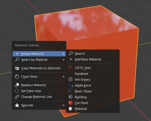
Change Atom Shape
It is possible to change the shape (sphere, cube, icosphere, etc.) and
material of the atoms. First, select your atoms in the 3D Viewport or the Outliner.
Shape
Choose the shape in the first selector.
Material
Choose one of the materials in the second selector. The materials are only examples,
further refinements can be done in the Materials tab of the Properties editor.
Special
Here, you can choose an object with a special shape, material, etc.
Such objects are quite nice to represent defects in atomic structures.
When choosing such a special object, you cannot anymore separately choose
the shape and material from above. In the Objects and Materials tabs of the Properties editor
further changes can be done.
Replace
After all, push the Replace button. The shape and/or material of all
selected atoms are then changed. This option works for objects and
instancing verts object structures.
Default
If you want to have the default values (NURBS spheres and specific element
colors and sizes) of selected atoms push the Default button.
Separate Atoms
When structures are imported via the PDB or XYZ importer, the atoms are put
into a so-called instancing verts structure, somewhat into ‘groups’ of elements
(e.g. all hydrogen atoms form one instancing verts structure). In the Edit Mode of Blender,
single atoms can be deleted or displaced by modifying the position of the vertices.
However, they are always a part of the structure and are not independent objects.
Sometimes one would like to mark a single atom or replace an atom by something different:
for instance, imagine you have a NaCl cube where you would like to replace an atom by
an atomic defect in form of a ball with a different color.
To separate single atoms, one needs to select the atom (vertices) first in the Edit Mode.
In the Atomic Blender Utilities panel, the Object selector and the Separate button appear at the bottom.
If the selector remains on Unchanged the type of object (NURBS, mesh, meta) and
its properties will not be changed upon separation. If desired also an other type of object can be chosen,
which then replaces the standard type of object.
After having chosen the type of object, use button Separate Atoms to separate the selected atoms:
the atoms are then single, new objects, which can be manipulated in any way.
They appear in the Outliner and carry the suffix _sep.
Hint
Converting All Atoms of a Instancing Verts Structure to Real Independent Objects
Do the following: Select the whole atomic structure with the mouse.
Go to objects Object ‣ Apply ‣ Make Instances Real.
With this you produce real independent objects! In the Outliner delete the remaining instancing verts structures,
named like “Carbon”, “Hydrogen”, etc.
Examples
Different presentations of one and the same molecule.
Part of a DNA molecule.
Functionalized [5]helicene molecules on the NaCl(001) surface
(Clemens Barth et al. –
Solar cell structure to underline the properties of silicon nanocrystals deposited by pulsed spray system
(Mickael Lozac’h et al. –
The following movie was created by Sébastien Coget (responsible researcher: Frank Palmino)
at the Femto-ST institute in Besançon (France).
The movie demonstrates that with Blender, professional movies can be done for research.
It was rendered with Cycles.
Stanford PLY
Reference
Category
Import-Export
Menu
File ‣ Import/Export ‣ Stanford (.ply)
Warning
Only one mesh can be exported at a time.
Properties
Import
The import does not have any properties.
Export
Include
Selection Only
Todo.
Transform
Forward / Up
Since many applications use a different axis for ‘Up’, these are axis conversion for these settings,
Forward and Up axes – By mapping these to different axes you can convert rotations
between applications default up and forward axes.
Blender uses Y Forward, Z Up (since the front view looks along the +Y direction).
For example, its common for applications to use Y as the up axis, in that case -Z Forward, Y Up is needed.
Scale
TODO.
Geometry
Apply Modifiers
Todo.
Normals
Todo.
UVs
Todo.
Vertex Colors
Todo.
Usage
Use the operator to import ASCII or binary PLY-files, you can select multiple files at once.
For exporting, you can choose to enable or disable the modifiers during the export
and you can choose which data you want to export (UV textures, vertex colors, …).
STL
Reference
Category
Import-Export
Menu
File ‣ Import/Export ‣ Stl (.stl)
This format is useful if you intend to import/export the files for CAD software.
It is also commonly used for loading into 3D printing software.
Warning
Currently the script does not handle importing or exporting of normals
and does not handle endianness, there is nothing in the STL specification about it.
Properties
Import
Transform
Scale
TODO.
Scene Unit
TODO.
Forward / Up Axis
Since many applications use a different axis for pointing upwards, these are axis conversion for these settings,
Forward and up axes – By mapping these to different axes you can convert rotations
between applications default up and forward axes.
Blender uses Y forward, Z up (since the front view looks along the +Y direction).
For example, it is common for applications to use Y as the up axis, in that case -Z forward, Y up is needed.
Geometry
Facet Normals
TODO.
Export
ASCII
TODO.
Batch Mode
TODO.
Include
Selection Only
TODO.
Transform
Scale
TODO.
Scene Unit
TODO.
Forward / Up Axis
Since many applications use a different axis for ‘Up’, these are axis conversion for these settings,
Forward and Up axes – By mapping these to different axes you can convert rotations
between applications default up and forward axes.
Blender uses Y Forward, Z Up (since the front view looks along the +Y direction).
For example, it’s common for applications to use Y as the up axis, in that case -Z Forward, Y Up is needed.
Geometry
Apply Modifiers
TODO.
Usage
Use the operator to import ASCII or binary STL-files, you can select multiple files at once.
For exporting you can select multiple objects and they will be exported as a single STL-file.
You can select between ASCII/binary file format (binary is more compact).
You can also choose to enable or disable the modifiers during the export.
UV Layout
Reference
Category
Import-Export
Menu
UV Editor ‣ UVs ‣ Export UV Layout
Usage
Using your favorite image painting program, you could use an exported UV layout to create a texture.
Then save your changes, and back in Blender, use the Image ‣ Open
to load it as your UV image for the mesh in Edit Mode for the desired (and active) UV map.
As a way of communicating to an artist who is painting your UV Texture for you,
Blender has a tool called UV Layout (UV Editor ‣ UVs ‣ Export UV Layout)
that saves an image as a Targa (.tga), EPS, or SVG format for the object you have selected.
The image will be lines defining the UV edges that are within the image area of the UV mapping area.
Edges outside the boundary, even if selected, will not be shown in the saved graphic.
The artist will use this as a transparent layer in their paint program as a guide when painting your texture.
The example below shows Blender in the background, and the Gimp working on the texture,
using the saved layout as a guide. Note that targa format supports the Alpha channel,
so you can paint transparent areas of the mesh. For using images as textures, see the page on
Image Textures.
A UV layout in the UV Editor.
A UV layout in a paint program.
Properties
Export options.
All UVs
if disabled, then only the UV faces selected will be outlined.
Modified
Export UVs from the modified mesh.
Format
Select the type of image file to save (.png, .eps, .svg).
Size
select the size of the image in pixels. The image be square.
Fill Opacity
Set the opacity of the fill.
Import & Export of Node Shaders
While Blender now only supports the advanced node-based shading model for its materials,
most IO formats only support a basic shading model,
similar to the legacy fixed pipeline of old GPUs.
Blender features a way to convert between those, which any add-on can use, but it is currently pretty basic still.
Especially for exporting from Blender materials, the node system must follow some strict requirements.
Note
Currently, only the
OBJ and
FBX
IO add-ons uses that method.
Note
The wrapper is designed to be as symmetrical as possible
(i.e. it is expected to give reproducible results across several import/export cycles).
A typical setup of shader nodes that is can be exported.
Supported Node Setup
This is especially important for exporting, importing will simply re-generate a similar setup.
Note that the features listed below are those supported by the wrapper.
Each add-on may have its own way to adapt them to its material system, some may not be handled by it, etc.
Principled BSDF
The main shader must be a Principled BSDF.
Only parameters defined there, and textures linked to it, will be exported.
Currently handled parameters:
Base color
Specular intensity
Specular tint (no texture support)
Roughness
Metallic
IOR
Transmission
Alpha
Normal Map
If linked to the Normal input of the Principled BSDF node,
the Normal Map node is also supported
(including its texture obviously).
Textures
Only Image textures using a UV mapping are supported.
You may also use a Mapping node to move/rotate/scale it.
Import Palettes
This add-on imports color palettes from Krita and Photoshop.
Todo.
Reference
Category
Import-Export
Menu
File ‣ Import Palettes
Paper Model
Reference
Category
Import-Export
Menu
File ‣ Export ‣ Paper Model (.pdf/.svg)
Panel
Properties editor ‣ Mesh ‣ Paper Model Islands
Menu
Mesh ‣ Unfold
This add-on generates a flat net of a given mesh.
It creates either PDF or SVG files suitable for direct printing and paper modeling.
The main goal is a maximal possible automation of the whole process.
Common tasks like baking the model’s texture into the output document are also supported.
Usage
To avoid eventual issues, switch to Object Mode.
Then, select the mesh you want to export so that it is the active one.
If you want to get results quickly, just execute this add-on from the File ‣ Export menu.
It will ask for a file name and do everything else automatically.
All relevant settings are in the bottom left corner.
These are described in more detail below.
If you are unhappy with the generated net, you can edit it manually.
For this, you have to execute the Unfold tool first (available Mesh tab in the Properties editor).
Edges that will be cut in order to flatten the mesh must be marked as Edit Mode seams.
You can use Clear Seam and Mark Seam tools to organize them as you wish,
or use the helper button Clear All Seams in Object Mode to start from scratch.
When you export the model, it will use all the given seams and add some more cuts if necessary.
You can also call the Unfold tool just for a preview of the net.
It will list all islands of the produced net in the panel and if you enable so in the tool’s settings,
it will also create a UV layout showing the islands.
Note that island positions are not calculated in this stage, so that they will all just lay on top of each other.
You can use Blender’s Pack Islands tool to arrange them.
There are a few kinds of topology that are possible in Blender but not in paper reality:
N-gon faces (everything except triangles) that are not perfectly flat.
Zero-length edges (two vertices exactly in the same spot and connected by an edge)
Zero-area faces (typically their vertices lie all in line)
If any of these cases is detected, the add-on will throw an error message and will not export.
The error message guides you how to fix the issues.
Exporting Textured Meshes
To export your model with a hand-painted texture, you have to unwrap the model, paint an image and
assign it to the model so that it has an effect during render.
You can use any tools you like for these tasks.
What the add-on does is simply that it uses baking in Textures mode.
Switch to Object Mode and deselect any objects except the one to be exported.
Then execute Export Paper Model and in the File Browser switch the Textures selector to From Materials.
If you choose to export a SVG file, you get several options how to attach the images.
All the options are explained in more detail Properties.
The resulting texture does not depend on any scene settings except for the given material,
and on the other hand, all settings should be intact after doing the export.
How to Read the Net
Most of the document’s appearance can be customized during export (see below).
However, the default style is supposed to be familiar to paper modelers:
dashed lines represent folding outwards, dash-dotted lines inwards (i.e., to form concave shapes).
Boundary of each part of the net is rendered in solid lines.
Sticking tabs have a grayish fill color to be distinguishable from other parts of the net.
A label is written on a tab when its target edge might not be clear.
Specifically, the label is omitted if the edge will be sticked to the same place as its both neighbors or
if one of these is the target itself.
The format of labels is island_abbreviation:edge_number.
Island abbreviation is written in square brackets under the corresponding island, before to its full-length name.
Edge number is written as a triangle arrow next to that target edge, outside the net.
If Create Tabs is disabled, the same format is used for labels along each of the related edges, inside the net.
This method is designed for modeling from hard and/or thick materials, for which sticking tabs are quite pointless.
If Create Numbers is disabled, the labels are omitted; this may be necessary for highly detailed models.
How to Print the Net
The PDF file can be directly printed almost anywhere.
However, things become difficult if you need to change the net by hand.
If you select the SVG format, you can edit the exported files in a vector graphics editor such as Inkscape.
One reason why you may want to do is to pack the islands manually and save paper.
Another reason is that the tabs and numbers often make a lot of clutter around the model and
it can be helpful to remove some of them by hand.
If printed document gets cropped around the page borders,
it means you should increase the Margin setting during export.
Placing Marks on the Net
Edges with a Freestyle Mark (Edge ‣ Mark Freestyle Edge) will be highlighted
in the net with a user-defined color and drawing style.
This is helpful especially when used on flat edges, which would normally not be drawn at all.
If you draw a shape with the Knife tool and then mark some of the edges as Freestyle ones,
you can make a simple line drawing on the model.
When used on folding edges, the highlight will be drawn below the folding line.
So you will probably have to change the Freestyle Lines drawing style to make it wider and not black,
so that the lines stay distinguishable.
Settings
Paper Model Islands
The Paper Model Islands tab in the Mesh tab offers two buttons for calling
the Unfold and Export Paper Model tools conveniently.
It also offers buttons for marking and clearing seams, depending on the context,
and the experimental functionality Limit Island Size.
Once the Unfold tool is called, the model is split into flattened parts and
these are presented in a list called Islands below.
The list allows you to change the label of each island.
If Create Numbers is enabled during export, abbreviations of these labels will be used to
describe which tab should be sticked to which island.
After running the Unfold tool, these island labels are recalculated so
that as many faces as possible remain under the same label.
If you select an island and enable the Highlight Selected Island button
(and the mesh you unfolded is the active one), the island will be highlighted in orange in the 3D View.
Using the slider below, you can change the opacity of the highlight.
Unfold
The first option from top is Create UV map.
If enabled, a new UV map will be generated to show all the islands.
However, their positions are not calculated yet at this time of the export process,
so they are all just placed in the bottom left corner.
This option is useful when editing the cutting lines by hand.
You can use the Unwrap tool and get a similar result.
The tool has three sliders, which all adjust edge cutting priority
(namely: Face Angle Convex, Face Angle Concave, Edge Length).
A high value gives an edge with the corresponding property a higher chance to be cut.
Because of that, it is usually better to set Edge Length to a negative value, letting long edges stay connected.
Randomly modifying these values may often help to reduce the count of islands in the net.
For information about the meaning of these values, read the Unfold section in the Technical Details.
Properties
When the export is initiated, the add-on silently unfolds the mesh (without marking any seams) and
divides all faces into islands, which may take a few seconds for complex meshes.
Then, a File Browser is displayed. With SVG format, the file name you choose will get a _page<number>.svg suffix,
even if only one page was needed.
Settings of this exporter are presented in the bottom left corner of the File Browser.
Preset
The Preset menu allows to quickly save and recall all the settings below it,
including model scale and color style.
Model Scale
Model Scale can be used to scale the whole net.
If you want to have a model in 1:72 scale, just set this to 72.
This is an important option also because the add-on often produces islands bigger than the page.
By default, this value is set so that even the biggest island fits onto the page.
If set to one, the real model will have the same dimensions as the virtual one.
Create UV map
Has a similar effect as the similar named option of the Unfold tool, but not the same.
It will create a new UV map that exactly reflects the placement of all the model’s islands.
Unfortunately, islands from all pages are placed on top of each other,
and it is quite impossible to tell them apart.
Document Settings
Settings closely related to the format of the output document are in the Document Settings sub-panel.
Format
First selector switches between PDF and SVG document formats.
Page Size
Another selector below allows you to choose one of the most common paper sizes quickly.
If you need something else, choose User Defined and set the dimensions manually.
Page Margin
Makes it easier to export models in exact scale (if you set the Model Scale slider to 1).
You can set it to the width of the non-printable border of your printer,
in order for the resulting SVG document to be printable without further scaling. However,
exporting in-scale models is still difficult, as the add-on does not automatically split oversize islands.
DPI
The next value is DPI, which defines the overall resolution of the net.
That is, not only resolution of baked images (if any), but also line thickness.
Create Tabs
Controls if the sticking tabs are created at all.
For example, uncheck this if you want to stick the model using tape.
Create Numbers
Adds numbers to some edge pairs that are supposed to be sticked together.
These numbers are excluded if the correct destination is easy to guess from the neighboring edges.
In more complex models, they may overlap a lot with each other and with the net itself.
Disabling this option may help solve such issues.
If Create Tabs is disabled, the numbers will be rendered inside of the net.
Tabs and Text Size
Sets the maximal width of the sticking tabs around islands.
The actual size of each tab is adjusted to be at most half the length of the corresponding edge.
In some special cases, tabs are made not to overlap with real faces, but it does not work reliably yet.
If Create Tabs is disabled, this slider controls the size of numbers on edges.
Hidden Edge Angle
Edges with folding angle below Hidden Edge Angle will not be drawn at all.
Increasing this value may produce nicer results when exporting smooth surfaces, such as cylinders:
it will spare a lot of unnecessary lines.
Decreasing it could possibly help in some special cases.
Textures
The Textures select menu lists options for exporting textured meshes.
No Texture
Just creates the net on a white background (this used to be called “Pure Net”).
The remaining options invoke texture baking and therefore are noticeable slower.
From Materials
Exports the image that is assigned to each of the model’s faces in their active material.
Full Render, Selected to Active
Correspond to the respective Bake Type options.
They both render all the materials and illumination: Full Render renders the model only,
while Selected to Active projects other nearby selected objects onto the model.
It may be helpful for creating patterns such as fur or leaves procedurally.
Images
The Images select menu allows you to choose how to include the baked images in the SVG file.
If you want to edit the layout of the net in an SVG editor, choose either Linked or Embedded.
Embedded
Creates standalone SVG files, making them bigger but portable.
Single Linked
Remains mostly for compatibility reasons.
Colors and Style
Options related to the drawing style are packed in the Colors and Style sub-panel.
They should be quite self-explanatory.
Technical Details
Unfold
Firstly, the algorithm assigns every edge a “priority”, depending on its angle and length.
Edges with higher priority will more probably be cut apart in the final net.
Shorter edges have higher priority (they are easier to glue on) and sharper angles too
(that makes the net easier to visually understand).
Faces form a concave angle if their normals are pointing against each other.
Such angles have even a bit higher priority which is supposed to help for typical models.
If some face normals are flipped, the algorithm always assumes the angle between them be convex.
If more than two faces are connected by an edge, two of them are designated as the main ones and
all others will have to be glued. The main faces are chosen so that they form the smallest angle possible.
The actual priority effect of angle versus length may change the resulting net very much.
The default values were chosen by trial and error for some basic models, but may be a bad choice for others.
If you want to tweak them, the Unfold tool allows you to: they are the tool’s three only settings.
The cutting algorithm begins with all faces separated and tries to connect them to form bigger islands,
ordered by the connecting edge’s priority. If some of the faces of the resulting island would overlap,
the operation is canceled and the algorithm continues with another edge.
If some vertices or edges end up close enough to each other, they are merged.
During this process, each edge is visited exactly once.
The overlap check is basically the Bentley-Ottmann algorithm for line segment intersection,
applied to the boundary of the resulting island. To handle some special cases,
the algorithm automatically switches between a slightly quicker and a more robust version of itself.
Another check is applied to detect if the boundary crosses itself in just a vertex of the resulting island –
such cases have to be tested explicitly as they need not cause any intersecting line segments.
Positioning the Nets on Pages
Because the nets are not consisting only of the real faces, but also of the gluing tabs around,
they cannot be positioned by the internal Blender tool (Pack Islands).
Therefore, a standalone algorithm had to be written.
For a great simplification of the process, all nets are packed into (smallest possible) bounding rectangles.
These are then ordered by size (largest first) and in this order the algorithm tries to position them on a page.
The positions tested for the lower left corner are given by an n × n grid resulting from
all the corners of islands already positioned. A position is accepted or rejected by checking overlaps
with each of the islands’ bounding rectangles.
When there are any islands left that could not be placed onto the page, a new free page is created.
This algorithm should work reliably and quite fast.
However, it is clearly inefficient if the bounding rectangles contain much free space.
Also, the packing depends heavily on the order in which the islands are processed, which is in no way optimal.
Pointcache (pc2)
Reference
Category
Import-Export
Menu
File ‣ Export ‣ Pointcache (.pc2)
This exporter produces pointcache files. These can be used to transfer animated meshes to external applications.
Only the vertex positions at the samples are saved.
The exporter can export meshes, surfaced curves, surfaces and font objects. They are all treated as meshes.
The base object has to be converted into a mesh before exporting it also.
Properties
Convert to Y-Up
Rotates the mesh data -90 degrees around X.
Export into World Space
Transform the mesh data into world space.
Apply Modifiers
Whether to apply modifiers before exporting.
Start Frame
First frame to export.
End Frame
Export up to this frame.
Sampling
The sample rate. 1 means one sample per frame. 0.1 means 10 samples per frame,
and 10 means one sample every 10 frames.
Importing
The use of these files depends on the importing application.
In general the object has to be first exported normally (OBJ export or the like) and
then the pointcache data can be attached to the object.
In 3ds Max there is a modifier which can directly read pc2 files.
In Maya the pc2 cache has to be converted into Maya’s geometry cache format first.
The MEL command for that is this:
DXF layers are reflected as Blender groups. This importer uses a general purpose DXF library called “dxfgrabber”.
DXF Type Mapping
To be as non-destructive as possible the importer aims to map as many DXF types to
Blender curves as possible.
DXF to Curves
LINE as POLYLINE curve (with the option to merge connecting lines).
(LW)POLYLINE, (LW)POLYGON as POLYLINE curve if they have no bulges else as BEZIER curve.
ARCs, CIRCLEs and ELLIPSEs as BEZIER curves.
HELIXes (3D) as BEZIER curves.
DXF to Meshes
MESH is mapped to a mesh object with a Subdivision Surface modifier, including the edge crease.
POLYFACEs and POLYMESHes are imported to a mesh object.
3DFACE s, SOLID s, POINT s are imported into one combined mesh object
per layer called layername_3Dfaces.
Missing DXF Types
Hatches
Leader
Properties
Merge Options
Blocks As
DXF Blocks can be imported as linked objects or group instances.
Linked objects use parenting for DXF sub-blocks (blocks in blocks).
Parent Blocks to Bounding Boxes
Draw a bounding box around blocks.
Merged Objects
Since Blender (v2.71) is pretty slow at adding objects the user might want to
merge similar DXF geometry to one object.
By Layer
Produces one object per layer; if there is mesh, curve, lamp, text data on one layer
one object per layer and per Blender object.
By Layer and DXF Type
The second not only differentiates between Blender data types but also DXF types,
such as LWPOLYLINE and POLYLINE.
By Layer and closed no-bulge polygons
Closed polylines with no bulge, that is no curved edges, can be merged to one single mesh.
This makes sense when the DXF polylines have an extrusion and/or an elevation attribute
which basically describes a location/rotation/scale transformation.
If this merge option is chosen, line thickness settings will be ignored/disabled.
By Layer and DXF-Type and Blocks
For DXF files with a block being referenced many times, this option allows to insert the same block many times
with one instanced-face object instead of with one object for each time the block needs to be inserted.
Unfortunately this works only for block inserts that are uniformly scaled.
Non-uniformly scaled block inserts are being imported as defined in Blocks As.
Combine LINE entities to polygons
Separated lines in DXF might be merged to one consecutive Blender poly curve.
Similar to Remove Doubles but for curves.
Line Thickness and Width
Represent Line Thickness/Width
DXF line attributes thickness and width have an effect on line in Z and X/Y direction respectively.
A straight line might be turned to a cube by its attributes for instance.
Therefore in Blender these attributes are represented with curve extrusion, bevel and taper objects.
Merge by Attributes
If both Merged Objects and Represent Line Thickness/Width are activated
the object merging needs to be extended to separate all lines width different thickness and width.
With Merge by Attributes this separation option is also available without
the actual representation of line thickness and width.
Optional Objects
Import TEXT
(TEXT, MTEXT)
Import LIGHT
Including support for AutoCAD colors.
Export ACIS Entities
Export NURBS 3D geometry (BODY, REGION, PLANESURFACE, SURFACE, 3DSOLID) to ACIS-Sat files,
since this is the format AutoCAD stores NURBS to DXF.
You are going to be notified about the amount of stored .sat/.sab files.
View Options
Display Groups in Outliner(s)
Switch the Outliner display mode to GROUPS (DXF layers are mapped to groups).
Import DXF File to a New Scene
Todo.
Center Geometry to Scene
Center the imported geometry to the center of the scene;
the offset information is stored as a custom property to the scene.
Georeferencing
Important: DXF files do not store any information about
the coordinate system / spherical projection of its coordinates.
Best practice is to know the coordinate system for your specific DXF file and
enter this information in the DXF importer interface as follows:
Pyproj
Installation: Download (Windows,
macOS) Pyproj and copy it to your
In case you need to compile your own binary refer to
this post
on Blender Artists.
Pyproj is a python wrapper to the PROJ library, a well known C library used to
convert coordinates between different coordinate systems.
Open source GIS libraries such as PROJ are used directly or indirectly by many authorities and
therefore can be considered to be well maintained.
If Pyproj is available the DXF importer shows a selection of national coordinate systems
but lets the user also to enter a custom EPSG / SRID code.
It also stores the SRID as a custom property to the Blender scene.
If a scene has already such a SRID property the coordinates are being converted from
your DXF file to target coordinate system and therefore you must specify a SRID for the DXF file.
If no SRID custom property is available the scene SRID is by default the same as the DXF SRID.
No Pyproj
In case Pyproj is not available the DXF importer will only use its built-in lat/lon to X/Y converter.
For conversion the “transverse Mercator” projection is applied that inputs a lat/lon coordinate to be used
as the center of the projection. The lat/lon coordinate is being added to your scene as a custom property.
Subsequent imports will convert any lat/lon coordinates to the same georeference.
Important: So far only lat/lon to X/Y conversion is supported.
If you have a DXF file with Euclidean coordinates that refer to another lat/lon center
the conversion is not (yet) supported.
Rules of thumb for choosing an SRID
if you have your data from OpenStreetMap or some similar GIS service website and
exported it with QGIS or ArcGIS the coordinates are most likely in lat/lon then use WGS84 as
your SRID with Pyproj or “spherical” if Pyproj is not available.
For other DXF vector maps it’s very likely that they use local / national coordinate systems.
Open the DXF with a text editor (it has many thousands of lines) and
make an educated guess looking at some coordinates.
DXF works with “group codes”, a name Autodesk invented for “key” as in key/value pairs.
X has group code 10, Y has 20, Z has 30. If you find a pattern like:
then NUMBER will be most likely your coordinates.
Probably you can tell from the format and/or the range of the coordinates which coordinate system it should be.
Export
Supported Data
Mesh face: POLYFACE or 3DFACE
Mesh edge: LINE
Modifier (optionally)
Unsupported Data
Mesh vertex: POINT
Curve: LINEs or POLYLINE
Curve NURBS: curved-POLYLINE
Text: TEXT or (wip: MTEXT)
Camera: POINT or VIEW or VPORT or (wip: INSERT(ATTRIB+XDATA))
This format is mainly use for interchanging character animations between applications
and is supported by applications such as Cinema4D, Maya, Autodesk 3ds Max, Wings3D and
engines such as Unity3D, Unreal Engine 3/UDK and Unreal Engine 4.
The exporter can bake mesh modifiers and animation into the FBX so the final result looks the same as in Blender.
Note
Bones would need to get a correction to their orientation
(FBX bones seems to be -X aligned, Blender’s are Y aligned),
this does not affect skinning or animation, but imported bones in other applications will look wrong.
Animations (FBX AnimStacks, Blender actions) are not linked to their object,
because there is no real way to know which stack to use as ‘active’ action for a given object, mesh or bone.
This may be enhanced to be smarter in the future, but it’s not really considered urgent,
so for now you’ll have to link actions to objects manually.
Armature instances are not supported.
Note
Bones’ orientation importing is complex, you may have to play a bit with
related settings until you get the expected results.
Animation support is minimal currently, we read all curves as if they were ‘baked’ ones
(i.e. a set of close keyframes with linear interpolation).
Imported actions are linked to their related object, bone or shape key, on a ‘first one wins’ basis.
If you export a set of them for a single object you’ll have to reassign them yourself.
Note
Saving Just Animations
The FBX file format supports files that only contain takes.
It is up to you to keep track of which animation belongs to which model.
The animation that will be exported is the currently selected action within the Action editor.
To reduce the file size, turn off the exporting of any parts you do not want and disable All Actions.
For armature animations typically you just leave the armature enabled which is necessary for
that type of animation. Reducing what is output makes the export and future import much faster.
Normally each action will have its own name but the current or
only take can be forced to be named “Default Take”. Typically, this option can remain off.
Note
Blender now only supports complex node-based shading. FBX having a fixed pipeline-like support of materials,
this add-on uses the generic wrapper
featured by Blender to convert between both.
Properties
Import
Include
Import Normals
TODO.
Import Subdivision Surface
Todo.
Import User Properties
TODO.
Import Enums As Strings
TODO.
Image Search
TODO.
Transform
Scale
Todo.
Decal Offset
TODO.
Manual Orientation
TODO.
Forward / Up Axis
Since many applications use a different axis for ‘Up’, these are axis conversion for these settings,
Forward and Up axes – By mapping these to different axes you can convert rotations
between applications default up and forward axes.
Blender uses Y Forward, Z Up (since the front view looks along the +Y direction).
For example, its common for applications to use Y as the up axis, in that case -Z Forward, Y Up is needed.
Apply Transform
TODO.
Use Pre/Post Rotation
TODO.
Animation
TODO.
Animation Offset
TODO.
Armature
Ignore Leaf Bones
TODO.
Force Connect Children
TODO.
Automatic Bone Orientation
TODO.
Primary/Secondary Bone Axis
TODO.
Export
Path Mode
When referencing paths in exported files you may want some control as to the method used since absolute paths
may only be correct on your own system. Relative paths, on the other hand, are more portable
but mean that you have to keep your files grouped when moving about on your local file system.
In some cases, the path doesn’t matter since the target application will search
a set of predefined paths anyway so you have the option to strip the path too.
Auto
Uses relative paths for files which are in a subdirectory of the exported location,
absolute for any directories outside that.
Absolute
Uses full paths.
Relative
Uses relative paths in every case (except when on a different drive on windows).
Match
Uses relative / absolute paths based on the paths used in Blender.
Strip Path
Only write the filename and omit the path component.
Copy
Copy the file on exporting and reference it with a relative path.
Embed Textures
TODO.
Batch Mode
When enabled, export each group or scene to a file.
Group/Scene
Choose whether to batch export groups or scenes to files.
Note, when Group/Scene is enabled, you cannot use the animation option Current Action
since it uses scene data and groups are not attached to any scenes.
Also note, when Group/Scene is enabled you must include the armature objects
in the group for animated actions to work.
Batch Own Directory
When enabled, each file is exported into its own directory,
this is useful when using the Copy Images option. So each directory contains
one model with all the images it uses. Note, this requires a full Python installation.
If you do not have a full Python installation, this button will not be shown.
Include
Selected Objects
Only export the selected objects. Otherwise export all objects in the scene.
Note, this does not apply when batch exporting.
Active Collection
Todo.
Object Types
Enable/Disable exporting of respective object types.
Custom Properties
TODO.
Transform
Scale
Scale the exported data by this value. 10 is the default
because this fits best with the scale most applications import FBX to.
Apply Scalings
TODO.
Forward / Up
Since many applications use a different axis for ‘Up’, these are axis conversions for Forward and
Up axes – By mapping these to different axes you can convert rotations between applications
default up and forward axes.
Blender uses Y Forward, Z Up (since the front view looks along the +Y direction).
For example, its common for applications to use Y as the up axis, in that case -Z Forward, Y Up is needed.
Apply Unit
TODO.
Apply Transform
TODO.
Geometry
Smoothing
TODO.
Export Subdivision Surface
Todo.
Apply Modifiers
When enabled, the mesh will be from the output of the modifiers applied to the mesh.
Loose Edges
TODO.
Tangent Space
TODO.
Armatures
Primary/Secondary Bone Axis
TODO.
Armature FBXNode Type
TODO.
Only Deform Bones
TODO.
Add Leaf Bones
TODO.
Bake Animation
TODO.
Key All Bones
TODO.
NLA Strips
TODO.
All Actions
Export all actions compatible with the selected armatures
start/end times which are derived from the keyframe range of each action.
When disabled only the currently assigned action is exported.
Force Start/End Keying
TODO.
Sampling Rate
TODO.
Simplify
TODO.
Compatibility
Import
Note that the importer is a new addition and lacks many features the exporter supports.
binary FBX files only.
Version 7.1 or newer.
Missing
Mesh: shape keys.
Export
NURBS surfaces, text3D and metaballs are converted to meshes at export time.
Missing
Some of the following features are missing because they
are not supported by the FBX format, others may be added later.
Object instancing – exported objects do not share data,
instanced objects will each be written with their own data.
Material textures
Vertex shape keys – FBX supports them but this exporter does not write them yet.
Animated fluid simulation – FBX does not support this kind of animation.
You can however use the OBJ exporter to write a sequence of files.
Constraints – The result of using constraints is exported as a keyframe animation
however the constraints themselves are not saved in the FBX.
Instanced objects – At the moment instanced objects are only written in static scenes
(when animation is disabled).
glTF 2.0
Reference
Category
Import-Export
Menu
File ‣ Import/Export ‣ glTF 2.0 (.glb, .gltf)
Usage
glTF™ (GL Transmission Format) is used for transmission and loading of 3D models
in web and native applications. glTF reduces the size of 3D models and
the runtime processing needed to unpack and render those models.
This format is commonly used on the web, and has support in various 3D engines
such as Unity3D, Unreal Engine 4, and Godot.
This importer/exporter supports the following glTF 2.0 features:
Meshes
Materials (Principled BSDF) and Shadeless (Unlit)
Textures
Cameras
Punctual lights (point, spot, and directional)
Animation (keyframe, shape key, and skinning)
Meshes
glTF’s internal structure mimics the memory buffers commonly used by graphics chips
when rendering in real-time, such that assets can be delivered to desktop, web, or mobile clients
and be promptly displayed with minimal processing. As a result, quads and n-gons
are automatically converted to triangles when exporting to glTF.
Discontinuous UVs and flat-shaded edges may result in moderately higher vertex counts in glTF
compared to Blender, as such vertices are separated for export.
Likewise, curves and other non-mesh data are not preserved,
and must be converted to meshes prior to export.
Materials
The core material system in glTF supports a metal/rough PBR workflow
with the following channels of information:
Base Color
Metallic
Roughness
Baked Ambient Occlusion
Normal Map
Emissive
An example of the various image maps available in the glTF 2.0 core format. This is
the water bottle sample model
shown alongside slices of its various image maps.
Imported Materials
The glTF material system is different from Blender’s own materials. When a glTF file is imported,
the add-on will construct a set of Blender nodes to replicate each glTF material as closely as possible.
The importer supports Metal/Rough PBR (core glTF), Spec/Gloss PBR (KHR_materials_pbrSpecularGlossiness)
and Shadeless (KHR_materials_unlit) materials.
Tip
Examining the result of the material import process is a good way to see examples of
the types of material nodes and settings that can be exported to glTF.
Exported Materials
The exporter supports Metal/Rough PBR (core glTF) and Shadeless (KHR_materials_unlit) materials.
It will construct a glTF material based on the nodes it recognizes in the Blender material.
The material export process handles the settings described below.
Note
When image textures are used by materials, glTF requires that images be in PNG or JPEG format.
The add-on will automatically convert images from other formats, increasing export time.
Tip
To create Shadeless (Unlit) materials, use the Background material type.
Base Color
The glTF base color is determined by looking for a Base Color input on a Principled BSDF node.
If the input is unconnected, the input’s default color (the color field next to the unconnected socket)
is used as the Base Color for the glTF material.
A solid base color can be specified directly on the node.
If an Image Texture node is found to be connected to the Base Color input,
that image will be used as the glTF base color.
An image is used as the glTF base color.
Metallic and Roughness
These values are read from the Principled BSDF node. If both of these inputs are unconnected,
the node will display sliders to control their respective values between 0.0 and 1.0,
and these values will be copied into the glTF.
When using an image, glTF expects the metallic values to be encoded in the blue (B) channel,
and roughness to be encoded in the green (G) channel of the same image.
If images are connected to the Blender node in a manner that does not follow this convention,
the add-on may attempt to adapt the image to the correct form during exporting (with an increased export time).
In the Blender node tree, it is recommended to use a Separate RGB node
to separate the channels from an Image Texture node, and
connect the green (G) channel to Roughness, and blue (B) to Metallic.
The glTF exporter will recognize this arrangement as matching the glTF standard, and
that will allow it to simply copy the image texture into the glTF file during export.
The Image Texture node for this should have its Color Space set to Non-Color.
A metallic/roughness image connected in a manner consistent with the glTF standard,
allowing it to be used verbatim inside an exported glTF file.
Baked Ambient Occlusion
glTF is capable of storing a baked ambient occlusion map.
Currently there is no arrangement of nodes that causes Blender
to use such a map in exactly the same way as intended in glTF.
However, if the exporter finds a custom node group by the name of glTFSettings, and
finds an input named Occlusion on that node group,
it will look for an Image Texture attached there to use as the occlusion map in glTF.
The effect need not be shown in Blender, as Blender has other ways of showing ambient occlusion,
but this method will allow the exporter to write an occlusion image to the glTF.
This can be useful to real-time glTF viewers, particularly on platforms where there
may not be spare power for computing such things at render time.
A pre-baked ambient occlusion map, connected to a node that doesn’t render but will export to glTF.
Tip
The easiest way to create the custom node group is to import an existing glTF model
that contains an occlusion map, such as
the water bottle
or another existing model. A manually created custom node group can also be used.
glTF stores occlusion in the red (R) channel, allowing it to optionally share
the same image with the roughness and metallic channels.
This combination of nodes mimics the way glTF packs occlusion, roughness, and
metallic values into a single image.
Tip
The Cycles render engine has a Bake panel that can be used to bake
ambient occlusion maps. The resulting image can be saved and connected
directly to the glTFSettings node.
Normal Map
To use a normal map in glTF, connect an Image Texture node’s color output
to a Normal Map node’s color input, and then connect the Normal Map normal output to
the Principled BSDF node’s normal input. The Image Texture node
for this should have its Color Space property set to Non-Color.
The Normal Map node must remain on its default property of Tangent Space as
this is the only type of normal map currently supported by glTF.
The strength of the normal map can be adjusted on this node.
The exporter is not exporting these nodes directly, but will use them to locate
the correct image and will copy the strength setting into the glTF.
A normal map image connected such that the exporter will find it and copy it
to the glTF file.
Tip
The Cycles render engine has a Bake panel that can be used to bake
tangent-space normal maps from almost any other arrangement of normal vector nodes.
Switch the Bake type to Normal. Keep the default space settings
(space: Tangent, R: +X, G: +Y, B: +Z) when using this bake panel for glTF.
The resulting baked image can be saved and plugged into to a new material using
the Normal Map node as described above, allowing it to export correctly.
See: Cycles Render Baking
Emissive
An Image Texture node can be connected to the Emission input on the Principled BSDF node
to include an emissive map with the glTF material. Alternatively, the Image Texture node
can be connected to an Emission shader node, and optionally combined with properties
from a Principled BSDF node by way of an Add Shader node.
If the emissive map is alone in the material, it is best to set the Base Color default
to black, and the Roughness default to 1.0. This minimizes the influence of the other
channels if they are not needed.
This arrangement is supported for backwards compatibility. It is simpler to use
the Principled BSDF node directly.
Double-Sided / Backface Culling
For materials where only the front faces will be visible, turn on Backface Culling in
the Settings panel of an Eevee material. When using other engines (Cycles, Workbench)
you can temporarily switch to Eevee to configure this setting, then switch back.
Leave this box un-checked for double-sided materials.
The inverse of this setting controls glTF’s DoubleSided flag.
Blend Modes
The Base Color input can optionally supply alpha values.
How these values are treated by glTF depends on the selected blend mode.
With the Eevee render engine selected, each material has a Blend Mode on
the material settings panel. Use this setting to define how alpha values from
the Base Color channel are treated in glTF. Three settings are supported by glTF:
Opaque
Alpha values are ignored.
Alpha Blend
Lower alpha values cause blending with background objects.
Alpha Clip
Alpha values below the Clip Threshold setting will cause portions
of the material to not be rendered at all. Everything else is rendered as opaque.
With the Eevee engine selected, a material’s blend modes are configurable.
Note
Be aware that transparency (or Alpha Blend mode) is complex for real-time engines
to render, and may behave in unexpected ways after export. Where possible,
use Alpha Clip mode instead, or place Opaque polygons behind only
a single layer of Alpha Blend polygons.
UV Mapping
Control over UV map selection and transformations is available by connecting a UV Map node
and a Mapping node to any Image Texture node.
Settings from the Mapping node are exported using a glTF extension named KHR_texture_transform.
There is a mapping type selector across the top. Point is the recommended type for export.
Texture and Vector are also supported. The supported offsets are:
Location - X and Y
Rotation - Z only
Scale - X and Y
For the Texture type, Scale X and Y must be equal (uniform scaling).
A deliberate choice of UV mapping.
Tip
These nodes are optional. Not all glTF readers support multiple UV maps or texture transforms.
Factors
Any Image Texture nodes may optionally be multiplied with a constant color or scalar.
These will be written as factors in the glTF file, which are numbers that are multiplied
with the specified image textures. These are not common.
Example
A single material may use all of the above at the same time, if desired. This figure shows
a typical node structure when several of the above options are applied at once:
A Principled BSDF material with an emissive texture.
Extensions
The core glTF 2.0 format can be extended with extra information, using glTF extensions.
This allows the file format to hold details that were not considered universal at the time of first publication.
Not all glTF readers support all extensions, but some are fairly common.
Certain Blender features can only be exported to glTF via these extensions.
The following glTF 2.0 extensions
are supported directly by this add-on:
Import
KHR_materials_pbrSpecularGlossiness
KHR_lights_punctual
KHR_materials_unlit
KHR_texture_transform
Export
KHR_draco_mesh_compression
KHR_lights_punctual
KHR_materials_unlit
KHR_texture_transform
Animation
glTF allows multiple animations per file, with animations targeted to
particular objects at time of export. To ensure that an animation is included,
either (a) make it the active Action on the object, (b) create a single-strip NLA track,
or (c) stash the action.
Supported
Only certain types of animation are supported:
Keyframe (translation, rotation, scale)
Shape keys
Armatures / skinning
Animation of other properties, like lights or materials, will be ignored.
An NLA Strip animation consists of multiple actions on multiple objects that
should play together. To create an NLA strip animation with the name “My Animation”,
push the action that should play each object onto an NLA track for
that object with the name “My Animation”.
Will be exported as an animation called “My Animation” with ConeAction
playing on the Cone and CubeAction playing on the Cube.
NLA Strip animations will be exported if the Animation ‣ NLA Strips option is
selected (on by default). All glTF animations are imported as NLA Strip animations.
If option is disabled, Blender NLA strip actions will be ignored.
Only active action of each objects will be taken into account, and merged into a single glTF animation.
Custom Properties
Custom properties on most objects are preserved in glTF export/import, and
may be used for user-specific purposes.
File Format Variations
The glTF specification identifies different ways the data can be stored.
The importer handles all of these ways. The exporter will ask the user to
select one of the following forms:
glTF Binary (.glb)
This produces a single .glb file with all mesh data, image textures, and
related information packed into a single binary file.
Tip
Using a single file makes it easy to share or copy the model to other systems and services.
glTF Separate (.gltf + .bin + textures)
This produces a JSON text-based .gltf file describing the overall structure,
along with a .bin file containing mesh and vector data, and
optionally a number of .png or .jpg files containing image textures
referenced by the .gltf file.
Tip
Having an assortment of separate files makes it much easier for a user to
go back and edit any JSON or images after the export has completed.
Note
Be aware that sharing this format requires sharing all of these separate files
together as a group.
glTF Embedded (.gltf)
This produces a JSON text-based .gltf file, with all mesh data and
image data encoded (using Base64) within the file. This form is useful if
the asset must be shared over a plain-text-only connection.
Warning
This is the least efficient of the available forms, and should only be used when required.
Folder to place texture files in. Relative to the gltf-file.
Copyright
Legal rights and conditions for the model.
Remember Export Settings
Store export settings in the blend-file,
so they will be recalled next time the file is opened.
Include
Selected Objects
Export selected objects only.
Custom Properties
Export custom properties as glTF extras.
Cameras
Export cameras.
Punctual Lights
Export directional, point, and spot lights. Uses the KHR_lights_punctual glTF extension.
Transform
Y Up
Export using glTF convention, +Y up.
Geometry
Apply Modifiers
Apply modifiers (excluding armatures) to mesh objects.
UVs
Export UVs (texture coordinates) with meshes.
Normals
Export vertex normals with meshes.
Tangents
Export vertex tangents with meshes.
Vertex Colors
Export vertex colors with meshes.
Materials
Export materials.
Images
Output format for images. PNG is lossless and generally preferred, but JPEG might be preferable for
web applications due to the smaller file size.
Compression
Compress meshes using Google Draco.
Compression Level
Higher compression results in slower encoding and decoding.
Quantization Position
Higher values result in better compression rates.
Normal
Higher values result in better compression rates.
Texture Coordinates
Higher values result in better compression rates.
Generic
Higher values result in better compression rates.
Animation
Use Current Frame
Export the scene in the current animation frame.
Animation
Exports active actions and NLA tracks as glTF animations.
Limit to Playback Range
Clips animations to selected playback range.
Sampling Rate
How often to evaluate animated values (in frames).
Always Sample Animations
Apply sampling to all animations.
NLA Strips
Whether to export NLA strip animations.
Export Deformation Bones Only
Export deformation bones only (and needed bones for hierarchy).
Shape Keys
Export shape keys (morph targets).
Shape Key Normals
Export vertex normals with shape keys (morph targets).
Shape Key Tangents
Export vertex tangents with shape keys (morph targets).
Skinning
Export skinning (armature) data.
Include All Bone Influences
Allow less than 4 joint vertex influences. Models may appear incorrectly in many viewers.
Contributing
This importer/exporter is developed through
the glTF-Blender-IO repository,
where you can file bug reports, submit feature requests, or contribute code.
Discussion and development of the glTF 2.0 format itself takes place on
the Khronos Group glTF Github repository,
and feedback there is welcome.
Wavefront OBJ
Reference
Category
Import-Export
Menu
File ‣ Import/Export ‣ Wavefront (.obj)
OBJ is a widely used de facto standard in the 3D industry.
The OBJ format is a popular plain text format, however, it has only basic geometry and material support.
Mesh: vertices, faces, edges, normals, UV’s
Separation by groups/objects
Materials/textures
NURBS curves and surfaces
Note
There is no support for mesh vertex colors, armatures, animation,
lights, cameras, empty objects, parenting, or transformations.
Note
Blender now only supports complex node-based shading. OBJ having a fixed pipeline-like support of materials,
this add-on uses the generic wrapper
featured by Blender to convert between both.
Warning
Importing very large OBJ-files (over a few 100mb), can use a lot of RAM.
OBJ’s export using Unix line endings \n even on windows,
if you open the files in a text editor it must recognize \n line endings.
Usage
Import/Export geometry and curves to the OBJ format.
If there is a matching .MTL for the OBJ then its materials will be imported too.
Properties
Import
Include
Image Search
This enables a recursive file search if an image file can’t be found.
Smooth Groups
Surround OBJ smooth groups by sharp edges.
Note that these will only be displayed when the Edge Split modifier is enabled.
Lines
Import OBJ lines and two-sided faces as mesh edges.
Transform
Clamp Size
OBJ-files often vary greatly in scale, this setting clamps the imported file to a fixed size.
Forward / Up
Since many applications use a different axis for ‘Up’, these are axis conversion for these settings,
Forward and Up axes – By mapping these to different axes you can convert rotations
between applications default up and forward axes.
Blender uses Y Forward, Z Up (since the front view looks along the +Y direction).
For example, it’s common for applications to use Y as the up axis, in that case -Z Forward, Y Up is needed.
Geometry
Split/Keep Vertex Order
When importing an OBJ it’s useful to split up the objects into Blender objects,
named according to the OBJ-file. However, this splitting looses the vertex order which
is needed when using OBJ-files as morph targets. It also looses any vertices that
are not connected to a face so this must be disabled if you want to keep the vertex order.
Split by Object & Split by Group
When importing an OBJ it’s useful to split up the objects into Blender objects,
named according to the OBJ-file. However, this splitting looses the vertex order which
is needed when using OBJ-files as morph targets. It also looses any vertices that
are not connected to a face, so this must be disabled if you want to keep the vertex order.
As far as Blender is concerned OBJ Objects and Groups are no difference,
since they are just two levels of separation,
the OBJ groups are not equivalent to Blender groups, so both can optionally be used for splitting.
Export
Include
Selected Objects
Only export the selected objects. Otherwise export all objects in the scene.
Objects as OBJ Objects / Groups
Write out each Blender object as an OBJ object.
Note
Note that as far as Blender is concerned there is no difference between OBJ Groups and Objects,
this option is only included for applications which treat them differently.
Material Groups
Create OBJ groups per material.
Animation
Exports a numbered OBJ for each frame from the start to the end frame.
Please be aware that this can take quite a long time.
Transform
Scale
Global scale to use on export.
Path Mode
When referencing paths in exported files you may want some control as to the method used since absolute paths
may only be correct on you’re own system. Relative paths on the other hand are more portable
but mean you have to keep your files grouped when moving about on your local file system.
In some cases the path doesn’t matter since the target application will search
a set of predefined paths anyway so you have the option to strip the path too.
Auto
Uses relative paths for files which are in a subdirectory of the exported location,
absolute for any directories outside that.
Absolute
Uses full paths.
Relative
Uses relative paths in every case (except when on a different drive on windows).
Match
Uses relative / absolute paths based on the paths used in Blender.
Strip Path
Only write the filename and omit the path component.
Copy
Copy the file on exporting and reference it with a relative path.
Forward / Up
Since many applications use a different axis for ‘Up’, there are axis conversion there settings,
Forward and Up axis – By mapping these to different axis you can convert rotations
between applications default up and forward axis.
Blender uses Y Forward, Z Up (since the front view looks along the +Y direction).
For example, its common for applications to use Y as the up axis, in that case -Z Forward, Y Up is needed.
Geometry
Apply Modifiers
Export mesh objects as seen in the 3D Viewport with all modifiers applied.
Mostly you will want this unless you are exporting a subdivision surface cage.
Smooth Groups
Todo.
Bitflag Groups
Todo.
Write Normals
Write out Blender’s face and vertex normals (depending on the faces smooth setting).
Mostly this isn’t needed since most applications will calculate their
own normals but to match Blender’s normal map textures you will need to write these too.
Include UVs
Write out the active UV layers coordinates from Blender.
Write Materials
Write out the MTL-file along with the OBJ. Most importers that support OBJ will also read the MTL-file.
Triangulate Faces
Write out quads as two triangles. Some programs only have very basic OBJ support and only support triangles.
Curves as NURBS
Write out NURBS curves as OBJ NURBS rather than converting to geometry.
Polygroups
Write faces into OBJ groups based on the meshes vertex group.
Note that this does a best guess since a face’s vertices can be in multiple vertex groups.
Keep Vertex Order
Maintain vertex order on export. This is needed when OBJ is used for morph targets.
Compatibility
NURBS surfaces, text3D and metaballs are converted to meshes at export time.
Missing
Some of the following features are missing:
NURBS Surfaces – this could be added but is not widely used.
Advanced Material Settings – There are material options documented
but very few files use them and there are few examples available.
Normals – Blender ignores normals from imported files, recalculating them based on the geometry.
Web3D X3D/VRML2
Reference
Category
Import-Export
Menu
File ‣ Import/Export ‣ X3D Extensible 3D (.x3d/.wrl)
Usage
TODO.
Properties
Import
Transform
Forward / Up Axis
Since many applications use a different axis for ‘Up’, these are axis conversions for
Forward and Up axes – By mapping these to different axes you can convert rotations
between applications default up and forward axes.
Blender uses Y forward, Z up (since the front view looks along the +Y direction).
For example, its common for applications to use Y as the up axis, in that case -Z forward, Y up is needed.
Export
Include
Selection Only
TODO.
Hierarchy
TODO.
Named Decorations
TODO.
H3D Extensions
TODO.
Transform
Scale
TODO.
Forward / Up
Since many applications use a different axis for pointing upwards, these are axis conversion for these settings,
Forward and up axes – By mapping these to different axes you can convert rotations
between applications default up and forward axes.
Blender uses Y forward, Z up (since the front view looks along the +Y direction).
For example, it is common for applications to use Y as the up axis, in that case -Z forward, Y up is needed.
Geometry
Apply Modifiers
TODO.
Triangulate
TODO.
Normals
TODO.
Compress
TODO.
NewTek MDD
Reference
Category
Import-Export
Menu
File ‣ Import/Export ‣ Lightwave Point Cache (.mdd)
Todo.
Dynamic Brush Menus
Activation
Open Blender and go to Preferences then the Add-ons tab.
Click Interface then Dynamic Brush Menus to enable the script.
Description
Provides access to commonly used settings and tools for painting/sculpting.
Features of Note:
Pop-ups to pick colors and edit curves.
A brush menu that supports user created brushes.
Sliders included at the top of sub-menus like Radius, Strength, and Weight to allow for precise adjustment.
Fast creation of UV maps and Texture Paint Slots in Texture Paint Mode if they are not already present.
A Preference for the number of columns shown in the Brush and Brush Mode menus can be found for
this add-on by going to the Add-ons tab in Preferences and expanding the add-on.
Reference
Category
Interface
Description
Fast access to brushes & tools in Sculpt and Paint Modes.
Location
Spacebar in Sculpt/Paint Modes
File
space_view3d_brush_menus folder
Author
Ryan Inch (Imaginer)
Maintainer
Ryan Inch (Imaginer)
License
GPL
Support Level
Community
Note
This add-on is bundled with Blender.
Dynamic Context Menu
Dynamic Context Menu provides access to many of the menus found in the 3D View header.
It also packs a few features of its own, such as the Cursor menu.
Access Operator Search, Tools, Animation, Quick Favorites, Modifiers, Collections and more.
It is context sensitive for the 3D View’s modes and object sensitive based on object selected in Edit Mode.
This add-on pairs well with the Dynamic Brush Menus.
Activation
Open Blender and go to Preferences then the Add-ons tab.
Click Interface then Dynamic Context Menu to enable the script.
Note
If you have trouble accessing the add-on in the interface:
You may need to set the Preferences ‣ Keymaps ‣ Spacebar Action to Tools
and save your preferences.
Reference
Category
Interface
Description
Object and mode context sensitive pop-up menu.
Location
3D View Spacebar
File
space_view3d_spacebar_menu folder
Author
meta-androcto
Maintainer
meta-androcto
License
GPL
Support Level
Community
Note
This add-on is bundled with Blender.
Copy Attributes Menu
This add-on extends the Copy ObjectsCtrl-C hotkey to include many extra copy types.
Activation
Open Blender and go to Preferences then the Add-ons tab.
Click Interface then Copy Attributes Menu to enable the script.
Description
Object Mode
Select more than one object, press Ctrl-C to copy attributes from active to selected,
you’ll see the following menu:
Each item on the menu will copy some attributes from the active (last selected object) to
all the other selected items:
Copy Location
Copies the object location in world coordinates.
Copy Rotation
Copies the object rotation in world coordinates.
Copy Scale
Copies the object scale in world coordinates.
Copy Draw Options
Copies draw options: for instance wireframe draw, empty draw shape, empty draw size, etc.
Copy Time Offset
Copies the animation stack time offset.
Copy Instancing
Copies the objects instancing group/vertex/face settings.
Copy Object Color
(Self-explanatory)
Copy Mass (physics setting)
(Self-explanatory)
Copy Protected Transform
Duplicates the transform locks.
Copy Object Constraints
Currently deletes all constraints on the selected objects and
replaces them with the constraints on the active object.
Copy Texture Space
(Self-explanatory)
Copy Pass Index
(Self-explanatory)
Copy Modifiers
Currently behaves like constraints, all you original modifiers will be replaced by the ones on the active item.
Copy Vertex Weights
(Self-explanatory)
Mesh Edit Mode
With a mesh object selected, enter Edit Mode and press Ctrl-C to copy texture face attributes.
The following menu appears:
Some of the items may not appear, depending on the number of UV texture or vertex color layers on the mesh.
The first group of options copies attributes from the active face to
all other selected faces in the same UV texture or vertex color layer.
Copy Material
Copy material index to selected faces.
Copy Image
Copy image assignment to selected faces.
Copy UV Coordinates
Copy UV coordinates to selected faces.
Copy Vertex Colors
Copy Vertex Colors to selected faces.
The second group of options copies attributes to selected faces in
the active UV texture or vertex color layer from their corresponding faces in
a different UV texture or vertex color layer.
Copy Image from Layer
Copy image assignment from another layer for selected faces.
Copy UV Coordinates from Layer
Copy UV coordinates from another layer for selected faces.
Copy Vertex Colors from Layer
Copy Vertex Colors from another layer for selected faces.
Pose Mode
Select more than one bone, press Ctrl-C to copy attributes from active (last selected bone) to
all other selected bones. The following menu appears:
Copy Local Location
Copies the location coordinate (as seen in the transform panel) to the selected bones.
Copy Local Rotation
Copies the rotation coordinate (as seen in the transform panel) to the selected bones.
Copy Local Scale
Copies the scale coordinate (as seen in the transform panel) to the selected bones.
Copy Visual Location
Copies the actual location of the bone (as seen in the screen) to the selected bones.
Copy Visual Rotation
Copies the actual rotation of the bone (as seen in the screen) to the selected bones.
Copy Visual Scale
Copies the actual size of the bone (as seen in the screen) to the selected bones.
Copy Bone Shape
(Self-explanatory)
Copy Protected Transform
(Self-explanatory)
Copy Pose Constraints
(Self-explanatory)
Copy IK Limits
(Self-explanatory)
Copy Pose
Is what was originally mapped to Ctrl-C before installing the add-on.
Distinction between Local and Visual
Local transformation of bones is relative the each bone’s own rest position;
if they do not match in Edit Mode, they will not match in Pose Mode,
even though the numbers appear the same in the bone’s transformation panel.
They also do not take into account constraints, or parenting.
Visual transformation of bones copies the visual transform (on screen) of
the active bone to the selected bones, regardless of parenting or constraints.
The result should look exactly the same even if the bone’s numbers do not match.
Constraints on the selected bones may prevent this from working (or drivers for that matter):
Reference
Category
Interface
Description
Copy Attributes Menu.
Location
3D Viewport Ctrl-C
File
space_view3d_copy_attributes.py
Author
Bassam Kurdali, Fabian Fricke, Adam Wiseman
Maintainer
to do
License
GPL
Support Level
Community
Note
This add-on is bundled with Blender.
Modifier Tools
A small collection of utilities for managing modifiers.
Activation
Open Blender and go to Preferences then the Add-ons tab.
Click Interface then Modifier Tools to enable the script.
Description
Apply All
Applies all modifiers on all selected objects in 3D Viewport.
This option is also available in the Apply menu.
Delete All
Removes all modifiers on all selected objects in 3D Viewport.
Viewport Visibility
Toggles viewport visibility on/off of modifiers for all selected objects in the 3D Viewport.
Some modifiers will be skipped as they don’t have their visibility exposed in the interface
(for example the Collision modifier). In that case, a message will be added with the modifier’s name.
Toggle Stack
Expands/collapses the stack of modifiers on the active object.
While in collapsed state, only the header of a panel is shown.
Usage
When enabled and the object has modifiers the additional helpers appear above the modifier stack.
Known Limitations
To access the options, the active object has to have modifiers.
Sometimes applying modifiers can fail for some objects.
For instance, if the modifier is disabled (i.e. Boolean Modifier that doesn’t have the Object field defined –
Mesh used for Boolean operation or objects that share linked data).
Reference
Category
Interface
Description
Modifiers specials show/hide/apply selected.
Location
Properties ‣ Modifiers
File
space_view3d_modifier_tools folder
Author
meta-androcto, saidenka
Maintainer
meta-androcto
License
GPL
Support Level
Community
Note
This add-on is bundled with Blender.
3D Viewport Pie Menus
Individual menu Activation. 13 individual menus to choose from.
Based on Pie menus from sebastian_k, pitiwazou, italic, saidenka, meta-androcto.
Since there are many hotkey changes each menu can be deactivated in the add-on’s preferences.
Activation
Open Blender and go to Preferences then the Add-ons tab.
Click Interface then 3D Viewport Pie Menus to enable the script.
Description
Animation Shift-Spacebar
This menu allows you to change the animation Play Settings from the viewport.
Apply Transforms Ctrl-A
This menu allows you to change the mode of the manipulator to move, rotate, scale or combination using.
Edit Align Alt-X
This menu allows you to align vertices/edges/faces to each other in Edit Mode.
Edit Delete X
Extended menu for deletion of vertices/edges/faces in Edit Mode.
Editor Switch Ctrl-Alt-S
Switch Editor Modes from any editor space.
Manipulator Menu Alt-Spacebar
Manipulator on off and combinations.
Mode Switch Ctrl-Tab
Switch between Object Type Modes.
Origin Ctrl-Alt-X
This menu allows you to move the cursor and set the object origin or pivot.
Save Open Ctrl-S
Save, Open, Import files menus.
Sculpt W
Easy open your Brushes with this pie menu.
Select A
Menu of selection types.
Shading Z
Shading viewport display.
View Numpad Q
Numpad View Directions.
Reference
Category
Interface
Description
Individual and optional pie menu activation.
Location
3D Viewport
File
space_view3d_pie_menus folder
Author
meta-androcto
Maintainer
meta-androcto
License
GPL
Support Level
Community
Note
This add-on is bundled with Blender.
Collection Manager
This add-on adds new functionality for the management of collections via a pop-up in the 3D Viewport.
It also offers a simple display and modification of the relationship of objects with collections.
Activation
Open Blender and go to Preferences then the Add-ons tab.
Click Interface then Collection Manager to enable the script.
Description
Use M call up the main Collection Manager pop-up in the 3D View when in Object Mode.
View Layer
Render
Enable/disable rendering of this view layer with this checkbox.
Local Restrictions (checkbox, cursor, eye, screen, camera icons)
LMB – Toggle collection restriction on/off.
Shift-LMB – Isolate the collection’s restriction, preserving parents if need be.
Click again to restore the previous state.
Ctrl-LMB – Toggles the restrictions of the collection and it’s children on/off.
Remove X
Remove the collection.
Filtering
By Name (box icon)
A text field to filter collections by name.
Invert (magnifying glass icon)
Invert filtering (inverts the collections shown in the tree view so that what is shown is hidden
and what was hidden is shown).
By Selected (box icon)
Filter collections by selected objects (show only collections that contain the selected objects).
Add Collection, Add Subcollection
Self-explanatory.
Phantom Mode
All visibility changes made in this mode will be discarded when it’s disabled.
Enabling Phantom Mode saves the current state of your restrictions and
allows you to edit them without fear of losing your current state.
When finished, disabling Phantom Mode will restore the saved state.
Note: You will be unable to edit anything other than the collections’ restrictions while in Phantom Mode.
Reference
Category
Interface
Description
Collection management system.
Location
3D Viewport
File
collection_manager folder
Author
imaginer (Ryan Inch)
Maintainer
imaginer
License
GPL
Support Level
Community
Note
This add-on is bundled with Blender.
Dynamic Sky
Dynamic Sky is an add-on to create a procedural sun and sky with lots of additional options to tweak.
With this single add-on you can create interior, exterior or any type of natural lighting with just a few clicks.
The Authors documentation can be found on
the author’s site.
Activation
Open Blender and go to Preferences then the Add-ons tab.
Click Lighting then Dynamic Sky to enable the script.
Interface
Located in the 3D View ‣ Sidebar ‣ Create tab.
Instructions
In the 3D View ‣ Sidebar ‣ Create tab press the Create button to run the script.
Open the Properties editor ‣ World tab and
choose Dynamic_1 in the World data-block menu.
Back in the Sidebar panel you will have new settings to adjust your sky.
You can also adjust the world settings in the Shader editor.
Reference
Category
Lighting
Description
Creates a Dynamic Sky for Cycles/Eevee.
Location
3D View ‣ Sidebar ‣ Create tab
File
lighting_dynamic_sky.py
Author
Pratik Solanki
Maintainer
Pratik Solanki
License
GPL
Support Level
Community
Note
This add-on is bundled with Blender.
Tri-Lighting
This add-on creates a simple three point studio style lighting set up.
Activation
Open Blender and go to Preferences then the Add-ons tab.
Click Lighting then Tri-Lighting to enable the script.
Interface
Located in the 3D View ‣ Add ‣ Light menu.
Usage
Select the object to point the lights at.
Add the lights with 3D View ‣ Add ‣ Light menu ‣ 3 Point Lights.
The created lights are pointed at and locked to the active object using a Track To constraint.
In the Properties editor ‣ Light tab you can further edit the properties of your lights.
Reference
Category
Lighting
Description
Add three point lighting to the selected or active object.
Location
3D View ‣ Add ‣ Lights
File
lighting_tri_lights.py
Author
Daniel Schalla
Maintainer
meta-androcto
License
GPL
Support Level
Community
Note
This add-on is bundled with Blender.
Sun Position
Sun Position allows positioning and animating the Sun (to a certain degree of accuracy),
to simulate real-world natural lighting. It uses physical characteristics to position the Sun in the scene:
geographic location, time and date. It is based on the Earth System Research Laboratory’s
online calculator.
Activation
Open Blender and go to Preferences then the Add-ons tab.
Click Lighting then Sun Position to enable the script.
Interface
Located in the Properties editor ‣ World ‣ Sun Position panel.
Usage
This add-on has two distinct modes of operation: the Normal Mode allows you to
animate the Sun realistically, while the Sun + HDRI Texture Mode is useful for
synchronizing a sun light to an HDRI texture.
The usage mode can be selected from the top of the Sun Position panel.
Normal Mode
This is the mode by default. After selecting the time and place, you can set up a sun light,
a sky texture, and a collection to serve as visualization.
Use Object
Select the sun object which will be placed according to the chosen time and place.
Its position will be updated every time you change the location or time,
and you can thus create animations by setting keyframes on them.
Use Collection
Select a collection of objects to be placed around the scene for visualization. Two options are available:
analemma and diurnal.
Note
It is recommended to create a collection in the scene,
and to move the objects into this collection. If you wish to create several visualizations,
create as many collections as needed, select them in turn and choose the right settings.
Once deselected, a collection will stay in place.
Analemma
The analemma is a visualization of
the position of the Sun in the sky around the year for a given time of the day.
In other words, it is like a time lapse picture of the sky over a year,
with the Sun appearing multiple times at the same time of the day.
The analemma was used here to match
Diurnal
This option allows you to visualize the trajectory of the Sun in the sky during a single day.
Sky Texture
Select a Sky Texture node in the World shading node tree.
It will be set up to match the sun animation.
This is useful if you want to have a simple sky texture matching a sun light’s position.
Location
In order for the Sun to be placed correctly, you need to choose a place on Earth where the scene is located.
This place is represented by two coordinates, Longitude (East / West) and Latitude (North / South).
They are expressed in degrees, from -180° to +180° for the longitude, and from -90° to 90° for the latitude.
The coordinates match those found on such databases as OpenStreetMap or Google Maps.
You may enter and animate them manually, or paste them in.
Entering Coordinates
In the Location panel, enter Latitude and Longitude coordinates corresponding to
the location you wish to simulate. A simpler way is to go to an online map such as OpenStreetMap,
copy the coordinates from there, and paste them into the Enter Coordinates field.
They will be parsed automatically.
Another source is Wikipedia. Suppose you want to render
the Barcelona Pavilion by Mies van der Rohe.
You can copy the coordinates from the article and paste them into Blender.
Using coordinates from Wikipedia.
Copy the coordinates from Wikipedia.
And paste them into Blender to have them parsed.
North Offset
By default, the North points to the Y axis in the scene (to the top of the screen in top view).
But sometimes, you may have modeled it in another orientation. In that case,
you may enter a North Offset, to change the orientation of the scene.
Show North toggles a dashed line pointing to the North in the 3D View,
to help you visualize the cardinal directions.
Setting the Time
After selecting the location on Earth, select or animate the date and time.
This is fairly straightforward, but care must be taken to match
the Time zone and Daylight Saving to the moment you wish to simulate.
Time entered is the local time, but the global, UTC time may be displayed below as well.
Note
Time is stored in decimal format instead of hour:minute:second.
To match a time in that format, look at the label Local.
Sun + HDRI Texture Mode
Instead of simulating the position of the Sun for a real location and time, this mode simply locks
an environment texture with a sun light object. It is useful if you want to increase the contrast in
a texture, by using an additional sun.
Synchronizing the Sun Object to the HDRI Texture
Start by selecting the sun object and Environment Texture node. You can then synchronize them by
enabling Sync Sun to Texture. Hovering any 3D View will display the environment texture.
Use the MMB to pan, scroll wheel to zoom, and Ctrl-MMB to set the exposure.
Zoom and click the center of the sun in the texture. After that, the sun object will be locked to it.
You can now rotate both the texture and the light by using the Rotation slider.
Click the sun in the environment texture in the 3D View to lock it to the sun light object.
Preferences
The preferences for the add-on make some features optional, so you can hide those you don’t use.
Reference
Category
Lighting
Description
Show Sun position with objects and/or sky texture.
Location
Properties editor ‣ World ‣ Sun Position panel
File
sun_position folder
Author
Michael Martin (xaire)
Maintainer
Damien Picard (pioverfour)
License
GPL
Support Level
Community
Note
This add-on is bundled with Blender.
Material Library
Materials Library VX is a Blender add-on that will create a material library.
You can save, load and categorize materials that can be shared across all your projects.
This version uses a blend-file as database so all external render engines,
all node materials and textures are supported. It also makes use of Blender compression.
See also
Please see author’s site
for the older original docs.
Activation
Open Blender and go to Preferences then the Add-ons tab.
Click Material then Material Library VX to enable the script.
Add-ons Preferences
Once the add-on is enabled you can open the preferences and
choose to set a path to use your own materials in the library.
Interface
Located in the Properties editor ‣ Materials ‣ Material Library VX.
Instructions
It’s advisable to add a fake user to your materials and
to save your blend-file before use.
New Library +
Create a new Library and name it. The new library will have one material to start.
Add to Library +
Add your materials to the library.
Apply to Selected (material icon)
Select a material in the list and apply it to the active object.
Reload Material (circular arrows icon)
Restore the saved version of the material if you want to revert edits.
Preview Material (palette icon)
Display the material in the materials Preview panel before adding it to the object.
Remove Preview (ghost icon)
Restore the Preview panel.
Remove Material -
Delete the active material from the Matlib VX list and your library.
Settings (wrench icon)
Extend the interface for some extra options.
Search
Search the library for a material.
Category Tools:
Here you can make sub categories.
Filter (funnel icon)
Apply the current filter.
Set Type (up arrow icon)
Apply the current selected category to the current material library.
Add +
Add a new category.
Remove -
Remove the current selected category from the list.
Reference
Category
Material
Description
Materials Library VX system for library creation.
Location
Properties ‣ Material
File
materials_library_vx folder
Author
Mackraken
Maintainer
meta-androcto
License
GPL
Support Level
Community
Note
This add-on is bundled with Blender.
Material Utilities
Materials Utilities/Specials is designed to help with batch materials tasks.
The add-on works in either Eevee or Cycles renderers.
Common tasks are available from the Shift-Q pop-up menu and also the Materials Specials menu.
Activation
Open Blender and go to Preferences then the Add-ons tab.
Click Material then Material Utilities to enable the script.
Add-ons Preferences
Choose the default settings for the add-ons actions here.
Interface
Located in the 3D View Shift-Q hotkey.
Located in the Properties editor ‣ Materials ‣ Specials.
Instructions
Assign Material +
Assign a material to the current selection. List of all materials and search for a material by name.
Select By Material (magnifying glass icon)
In Edit or Object Mode you can select based on material.
Faces with chosen material will become selected.
All objects with a chosen material will be selected in Object Mode.
Copy Material to Selected (ID icon)
Copy the material from the active object to selected objects.
Clean Slots (glossy sphere icon)
Clean Material Slots X
For all selected objects, removes all empty and unused material slots (not assigned to any polygons).
Due to Blender’s current limitations, available only in Object Mode
(the option will be grayed out in Edit Mode).
Remove Active Material Slots -
Todo.
Remove All Material Slots (X)
Removes All material slots of the active object.
Replace Material (overlay icon)
Replace a material by name. Lets your replace one material by another.
Optionally for all objects in the blend, otherwise for selected editable objects only.
An additional option allows you to update object selection, to show which objects were affected and which not.
Set Fake User (shield icon)
Lets you set all the materials to have a fake user. This is very useful when saving materials for use later.
Further comprehensive documentation can be found in the co-author’s
Github repository.
Reference
Category
Material
Description
Menu of material tools (assign, select..) in the 3D View.
Location
3D View Shift-Q
File
materials_utils folder
Author
MichaleW, ChrisHinde
Maintainer
MichaleW, ChrisHinde
License
GPL 3+
Support Level
Community
Note
This add-on is bundled with Blender.
3D Print Toolbox
Reference
Category
Mesh
Description
Utilities for 3D printing.
Location
3D View ‣ Sidebar
File
object_print3d_utils folder
Author
Campbell Barton
Installation
This add-on is bundled with Blender.
Open Blender and go to Preferences then the Add-ons tab.
Click Mesh then 3D Print Toolbox to enable the script.
Description
To Do
Auto Mirror
Todo.
See also
Please see the
old Wiki
for the archived original docs.
Activation
Open Blender and go to Preferences then the Add-ons tab.
Click Mesh then Auto Mirror to enable the script.
Usage
In Object Mode, select the object you want to mirror.
Choose settings from the Auto Mirror panel in the Sidebar ‣ Edit tab.
Press Auto Mirror and depending on the settings, your object will be in Edit Mode, with mirror set up for you.
Reference
Category
Mesh
Description
Super fast cutting and mirroring for mesh.
Location
View 3D ‣ Sidebar ‣ Edit tab
File
mesh_auto_mirror.py
Author
Lapineige
License
GPL
Note
This add-on is bundled with Blender.
Bsurfaces GPL Edition
Todo.
Activation
Open Blender and go to Preferences then the Add-ons tab.
Click Mesh then Bsurfaces GPL Edition to enable the script.
Reference
Category
Mesh
Description
Modeling and retopology tool.
Location
3D View Edit Mode ‣ Sidebar ‣ Edit tab
File
mesh_bsurfaces.py
Author
Eclectiel, Spivak Vladimir (cwolf3d)
Edit Mesh Tools
Mesh Edit Tool adds several tools to Blender that are not available in the built-in tools or
provide different methods for similar tasks.
Each Menu: Vertex, Edge, Face and Utility is a sub panel that is closed
by default in the Sidebar ‣ Edit tab.
The Icons in the closed panel headers contain some new/different selection tools and
Edit Mode vertex/edge/face selection modes for quick access to some tools, before opening the sub panels.
In the UI there’s a variety of tools in each category, most tools have a tooltip to provide
some usage information to help users understand each tools basic requirements.
‘Most significant hotkeys is in Edit Mode double RMB-click brings up the Vertex/Edge/Face menus
depending on vertex/edge/face selection mode.
Menu Integration is main tools into the Edit Mode context menu, selection tools into the Edit Mode select menu.
Face Inset Fillet: based completely on add-on by zmj100
Vertex Align: by zmj100
Edge Fillet Plus: by Gert De Roost – original by zmj100
Split Solidify: by zmj100, updated by zeffii to BMesh
Pen Tool: by zmj100
Mesh Cut Faces: by Stanislav Blinov (Stan Pancakes)
Vertex/Edge/Face Context Menu: by Stanislav Blinov (Stan Pancakes)
Edge Roundifier: by Piotr Komisarczyk (komi3D), PKHG
PKHG Face Extrude: by PKHG, based on Geodesic Domes add-on “faces function”
Set Edges Length: by “Giuseppe De Marco [BlenderLab] inspired by NirenYang”
Edge Tools: by Paul Marshall (brikbot)
Extrude and Reshape: by Germano Cavalcante (mano-wii)
Fast Loop: by Andy Davies (metalliandy)
Multi Extrude: by Liero, Jimmy Hazevoet
Offset Edges: by Hidesato Ikeya
Mesh to Wall: by luxuy_BlenderCN
Vertex Chamfer: by Andrew Hale (TrumanBlending)
Random Vertices: by Oscurart
Select Tools: by dustractor
Thanks to Macouno and CoDEmanX
Activation
Open Blender and go to Preferences then the Add-ons tab.
Click Mesh then Edit Mesh Tools to enable the script.
Description
Todo.
See also
Please see the
old Wiki
for the archived original docs.
Extrude & Reshape
You can select a face and extrude it inwards or outwards, creating new faces to accommodate the extrusions.
Note: Also known as Push/Pull Face.
Reference
Category
Mesh
Description
Mesh modeling toolkit. Several tools to aid modeling.
Location
3D View ‣ Sidebar ‣ Edit tab, 3D View Edit Mode ‣ context menu
File
mesh_tools folder
Author
Multiple Authors, Meta-Androcto
Maintainer
meta-androcto, lijenstina
License
GPL
Note
This add-on is bundled with Blender.
F2
F2 (also known as the ‘spider-script’) extends Blender native functionality of creating faces.
It allows you to create a face from a single vertex selection or a single edge selection,
while retaining all the built-in functionality.
Activation
Open Blender and go to Preferences then the Add-ons tab.
Click Mesh then F2 to enable the script.
Description
Quad from Vertex
When a single vertex is selected, a new quad is formed by creating a new vertex.
The position of this new vertex is calculated based on the three existing vertices.
These are the selected vertex, and two vertices to which it is connected via open edges.
An open edge is an edge which is only part of one face, or none at all.
The newly created quad has the same material and normal direction as the neighboring faces.
Quad from Edge
Similar to the quad from vertex functionality, this is based on open edges.
The selected edge has to be connected to two open edges.
The vertices which belong to these edges are used to create a new quad.
Direction Control
If there are multiple ways to create a new quad, the position of the mouse cursor is taken into account.
Of the multiple new faces which are possible, the one which will be closest to
the mouse cursor (in 2D screen space) is the one which will be created.
Reference
Category
Mesh
Description
Extends the ‘Make Edge/Face’ functionality.
Location
Mesh Edit Mode F
File
mesh_f2.py
Author
Bart Crouch, Alexander Nedovizin, Paul Kotelevets (concept design), Adrian Rutkowski
License
GPL
Note
This add-on is bundled with Blender.
Inset Straight Skeleton
This add-on makes ‘inset polygons’, which you get when you advance the edges of
the polygon inwards at a constant rate. Sometimes when you do that, an advancing edge shrinks to nothing,
or edges hit an advancing concave corner. The algorithm tries to do the right thing when this happens:
one or more new polygons may form at that point, and insetting can continue inside those new polygons.
You can either inset a single polygon or you can treat groups of polygons connected together as a single region,
forming a complicated polygon (that may include holes) to be insetted as a unit.
In addition to insetting, it is often useful to raise or lower the inset polygon (perpendicular to the inset plane),
so a parameter to do that is included also.
Activation
Open Blender and go to Preferences then the Add-ons tab.
Click Mesh then Inset Straight Skeleton to enable the script.
Description
Enter mesh Edit Mode on a mesh object, and select one or more faces.
Scale
Percent
Means that amounts are a percentage of the amount for a full inset.
Absolute
Means that the amounts are in units.
Amount
The distance to move the edges inward.
Height
The distance to move the inset polygons upward.
Region
If checked, treat all selected faces as a region to be inset, otherwise inset each face individually.
Quadrangulate
Todo.
Technical Details
The method used is described on
the Straight Skeleton Wikipedia page.
Consider this starting polygonal region:
As the edges move inward at a constant speed, two kinds of events can happen.
One is that an advancing corner can hit an advancing edge, as seen on the right part of this picture:
When this happens, the inset polygon splits into two.
The other is that an advancing edge can shrink to a point.
When the whole process continues until the end, you get something like this:
One cool thing about this algorithm is that if you move upwards or downwards
(perpendicular to the inset plane) at a constant speed, you form ‘roofs’ with a fixed pitch.
See also
Please see the
old Wiki
for the archived original docs.
Reference
Category
Mesh
Description
Make an inset inside selection using straight skeleton algorithm.
Location
3D View Operator
File
mesh_inset folder
Author
Howard Trickey
License
GPL
Note
This add-on is bundled with Blender.
Loop Tools
Todo.
Activation
Open Blender and go to Preferences then the Add-ons tab.
Click Mesh then Loop Tools to enable the script.
Description
Bridge
There are two main ways to use the Bridge tool, both of which are illustrated in the image below.
The first method is to select two groups of faces and then run the tool.
The second method is to select two (closed) loops of edges.
Both methods can be mixed and you can even Bridge multiple groups at the same time.
The script will try to make an educated guess on which groups should be connected.
Bridge shares its settings with the Loft tool, so changing a setting for one of the tools,
will also change it for the other tool.
Segments
The number of faces used to bridge the distance between two loops.
One segment means that only faces will be created.
Two (or more) segments means that an intermediary line (or lines) of vertices is created,
so two or more faces can be defined between the loops. If the value is set to zero,
the script automatically calculates the best amount of segments in order to keep the faces as square as possible.
Minimum Width
This option has no label, but is located directly to the right of the segments setting.
The simple explanation: 0% lot of triangles, 100% mostly square faces. There is a bit more to it though.
It determines when a new vertex has to be created, or when to use the vertex next to it.
It does this based on the distance between these vertices compared to the distance between
the vertices in the original loops. So 50% means that if the distance between two vertices
that will be newly created is smaller than half the distance between two vertices in the original loop,
they will be merged together, resulting in only a single new vertex. This is also demonstrated in the video above.
Interpolation
This can be set to either cubic or linear. Linear is just a flat interpolation,
while cubic tries to retain the surface tangents, resulting in more fluid curves.
Strength
The strength option is only available when the interpolation mode is set to cubic.
Setting the strength to zero gives a result very similar to linear interpolation,
while higher strengths result in more fluid curves.
Setting a negative strength changes the direction of the curve. Or described in a more visual way:
it makes deflated volumes inflate and vice versa. The soft limits of this option are set to range from -3 to +3,
but you can easily assign bigger or smaller values by manually entering a number, instead of using the slider.
This works just the same as with normal sliders in Blender.
Remove Faces
When using a face-selection input, the inner faces will be removed after bridging.
Because of some limitations in Blender the weight values assigned to
the Bevel modifier might be slightly altered (by about 0.01) when this option is enabled.
Twist
Determines which vertices in both loops are connected to each other.
This might be used for artistic reasons or to correct a wrong result given by the script.
Reverse
This option should only be used if the script gives a wrong result.
It reverses the order in which vertices are connected and can fix problems
when the script gives a result that looks inverted. It’s a bit hard to describe,
but just try it once and you’ll immediately understand what it does.
Creating Holes
You can additionally create holes in an object via the Bridge tool.
Select two or more faces and run the Bridge tool.
Circle
There are two correct inputs for the circle tool: selecting a single vertex,
or selecting a closed or open loop of edges.
You can also have the tool operate on multiple inputs at the same time and mix the input types.
Method
Best Fit
When Best Fit is selected a circle is calculated using a non-linear least squares method.
This basically means that the circle that is calculated with this option best fits the vertices you selected.
Fit Inside
Selecting Fit Inside will calculate the circle in such a way
that none of the vertices will be moved away from the center of the calculated circle.
This is useful when you want to retain the topology of the surrounding mesh.
Flatten
When enabled, the input will be flattened to an optimal plane.
This includes the center vertex, if the input consisted of a single vertex.
When disabled the input will be projected onto the existing mesh.
Radius
This overrides the radius calculated by the script.
Useful if you wish to create several circles of the same size, or if you need more precision.
Regular
When this option is selected, the vertices on the circle will all have the same distance between each other.
Influence
The force of the tool. Zero percent influence means no changes will be made to the mesh.
100% influence means that the input will be fully transformed into a circle.
Curve
There are two valid input methods for the curve tool.
The first is to select two or more vertices on the same loop.
You can do this for multiple loops simultaneously to save time.
The second method is to select one or more entire loops.
If a full loop is selected, the curve tool won’t operate on that loop,
but on all loops perpendicular to it and use the vertices on the selected loop(s) as control points.
Interpolation
Cubic gives a smooth curve, calculated using a natural cubic spline algorithm.
Linear calculates straight lines through the control points.
Restriction
This restricts the movement of the vertices to only one direction.
Indent only allows movement toward the mesh,
while extrude only allows movement away from the mesh (in the direction of the normal).
Boundaries
If enabled, the curve won’t stretch beyond the input vertices.
This limits the tool to only a subsection of the mesh.
Regular
This will evenly distribute the vertices along the curve. Sometimes this can create weird results,
as an even distribution isn’t always possible (since the selected input vertices aren’t moved).
If that is the case, simply uncheck this checkbox.
Influence
The force of the tool. Zero percent influence means no changes will be made to the mesh.
100% influence means the tool will have the maximum effect.
Flatten
Any selection is considered acceptable input for the flatten tool.
Plane
The method used to calculate the plane on which the input is flattened.
Best fit
Calculates a plane so that on average the vertices will have to be moved the least to be flattened.
Normal
Is identical to scaling the input to zero on local Z when the orientation is set to normal (so G Z Z 0).
It’s mainly included for making an easy comparison between the flatten methods.
View
Flattens the input on a plane perpendicular to the viewport angle. So when you run the tool,
it will appear nothing has changed, but when you rotate the viewport, you’ll see what has happened.
Influence
The force of the tool. Zero percent influence means no changes will be made to the mesh.
100% influence means the input will be fully flattened.
Loft
For loft you can use the same input method as for Bridge: selecting groups of faces, or selecting (closed) loops.
You can mix input methods. Contrary to Bridge, you can select more than two input groups,
and have them bridged consecutively.
Loft shares its settings with the Bridge tool, so changing a setting for one of the tools,
will also change it for the other tool. For a full discussion of all the settings take a look at the Bridge settings.
Below you’ll find some specific information for the loft tool.
Segments
This is identical to the Segments setting of the Bridge tool,
but setting it to automatic (segments = 0) has an advantage for the loft tool.
When letting the script determine the number of segments needed,
it might create different numbers of segments between different loops.
Loop
Connects the first and the last loop to each other.
Relax
The input of the relax tool consists of a single (partial) loop.
Interpolation
Determines how the final position of the vertices is calculated.
Cubic uses a natural cubic spline to project the vertices on, linear projects the vertices on straight lines.
A word of caution: when you use the relax tool on a closed loop
(a loop where all vertices are connected to two other vertices in the same loop)
you can better use cubic interpolation instead of the linear.
If you use linear interpolation, the volume of the loop will quickly diminish.
Input
Selection
When set to Selection the tool will only operate on the selected vertices.
Parallel (all)
Setting it to Parallel (all), will also include the vertices of all parallel loops.
Iterations
The number of times the tool is run. A higher number gives a smoother result.
Regular
If this option is selected, the vertices will be distributed evenly along the loop.
Space
The input of the space tool consists of a single (partial) loop.
Interpolation
Cubic distributes the vertices along a natural cubic spline through,
while linear projects the vertices on the already existing edges.
Input
Selection
When set to Selection the tool will only operate on the selected vertices.
Parallel (all)
Setting it to Parallel (all), will also include the vertices of all parallel loops.
Influence
The force of the tool. Zero percent influence means no changes will be made to the mesh.
100% influence means the tool will have the maximum effect.
See also
For an illustrated explanation of all the tool settings visit
the script homepage.
Please see the
old Wiki
for the archived original docs.
Reference
Category
Mesh
Description
Mesh modeling toolkit. Several tools to aid modeling.
Location
3D View ‣ Sidebar ‣ Edit tab, 3D View Edit Mode ‣ context menu
File
mesh_looptools.py
Author
Bart Crouch
License
GPL
Note
This add-on is bundled with Blender.
Relax
This script relaxes the selected vertices while retaining the shape as much as possible.
Activation
Open Blender and go to Preferences then the Add-ons tab.
Click Mesh then Relax to enable the script.
Usage
Go into Edit Mode and select the vertices you want to relax.
To execute the script either Context Menu ‣ Relax
or use Mesh ‣ Vertices ‣ Relax instead.
Reference
Category
Mesh
Description
Relax the selected vertices while retaining the shape.
Location
3D View ‣ Edit Mode Context Menu ‣ Relax
File
mesh_relax.py
Author
Fabian Fricke
License
GPL
Note
This add-on is bundled with Blender.
Snap Utilities Line
Reference
Category
Mesh
Description
Extends Blender Snap controls.
Location
3D View ‣ Tools ‣ Line Tool
File
mesh_snap_utilities_line folder
Author
Germano Cavalcante
Installation
This add-on is bundled with Blender.
Open Blender and go to Preferences then the Add-ons tab.
Click Mesh then Snap Utilities Line to enable the script.
Description
To Do
tinyCAD Mesh Tools
The add-on is a combination of several scripts which should be useful to anyone
who has used other CAD software for drafting with some level of precision.
The context menu has the tinyCAD functions prepended to it.
Activation
Open Blender and go to Preferences then the Add-ons tab.
Click Mesh then tinyCAD Mesh tools to enable the script.
Description
VTX
Automatically extends, projects or intersects the two selected edges if they are co-planar.
For auto VTX you must be in (Edit Mode and edge mode) and have two edges selected.
When invoked the add-on will detect if you are trying to intersect, project or extend two edges.
It will internally pick from V, T or X. It will also notify you if the edge are not co-planar / do not intersect.
V: Extending two edges towards their calculated intersection point.
T: Extending the path of one edge towards another edge.
X: Two edges intersect, their intersection gets a weld vertex. You now have four edges and five vertices.
V2X
Places a new separate vertex at projected intersection of two selected edges.
XALL
This mass intersects a collection of edges. Pick a collection of edges and invoke XALL.
It will deselect any edge that doesn’t intersect other edges first.
Then it goes through all combinations of the remaining edges to see if there are intersections.
Each intersection is dealt with and the result is added to the collection of edges to check.
This process continues until no more intersections are found.
BIX
Given two selected edges, this script creates the bisector of these edges.
The edges are first checked for co-planarity.
CCEN
Construct a circle and its center.
Pick three vertices that once made up a circle, then W ‣ CCEN,
the script adds a Grease Pencil representation of the circle.
To add a mesh of that constructed circle you can press F6 straight afterwards and
adjust the circle’s vertex count. Then press Make Circle Mesh to add a new circle.
This is a little bit experimental, but works fine.
Reference
Category
Mesh
Description
Mesh modeling toolkit. Several tools to aid modeling.
Location
3D View Edit Mode ‣ context menu
File
tiny_cad folder
Author
zeffii (Dealga McArdle)
License
GPL
Note
This add-on is bundled with Blender.
Tissue
The add-on is composed by different tools for computational design.
Activation
Open Blender and go to Preferences then the Add-ons tab.
Click Mesh then Tissue to enable the script.
Description
Tessellate
The Tessellate tool allows the user to copy a selected object (Component) on the faces of
the active object (Generator), adapting its bounding box to the shape of quad faces.
Once the Tessellate button was pressed, then more options will appear in the tool parameters.
Update allows you to update the active the Tessellated mesh according to Component and Generator changes.
You can also change the parameters of tessellation.
New Object Name
Specify the name of the new object generated by the Tessellate tool.
Generator:
Fill Mode
Allows to chose the filling method.
Quad
For quadrangular meshes Quad option is preferable.
Fan
While for polygonal meshes Fan works better.
Merge
Removes duplicated vertices according to threshold value.
Randomize
Create a random of the components according to seed.
Component:
Component XY
Allows to chose how the component object is parametrized.
Adaptive
Automatically calculate the Bounding Box of the object.
Constant
For more control chose Constant, that consider a domain in which X and Y go from 0.0 to 1.0.
Component Z
Allows to chose how the thickness is calculated.
Constant
Uses the Z of the component.
Proportional
Using Proportional the Z of generated components changes according to generator faces area.
Warning
Using Proportional can create some openings if used with Merge options.
Scale
Allows to change thickness of the generated mesh.
Offset
Allows to offset the thickness from the center.
Update
The options for the Update tool are the same of Tessellate.
Furthermore, it allows to change Generator object and Component object.
Colors-Weight Exchanger
The Colors-Weight Exchanger consists of two tools: Colors from Weight and Weight from Colors
that allow the user to convert the active vertex color to vertex group and vice versa.
Colors from Weight
Convert to
Value Channel, Red Channel, Green Channel, Blue Channel, False Color
Invert
Invert the values read from vertex weight.
Weight from Colors
Red Channel
Add a vertex group derived to red channel of the active vertex color.
Green Channel
Add a vertex group derived to green channel of the active vertex color.
Blue Channel
Add a vertex group derived to blue channel of the active vertex color.
Value Channel
Add a vertex group derived to value channel of the active vertex color.
Invert
Invert the values read from vertex weight.
Dual Mesh
Dual Mesh modifies the selected meshes creating dual meshes.
Dual Mesh output is a polygonal mesh derived from the triangular mesh.
Quadrangular meshes are automatically converted to triangular before.
Quad Method
Methods for splitting the quads into triangles. (Inherited from the Triangulate Faces tool.)
Polygon Method
Methods for splitting the polygons into triangles. (Inherited from the Triangulate Faces tool.)
Preserve Borders
Prevent alteration of the open boundaries of the mesh.
Example
Reference
Category
Mesh
Description
Tools for computational design.
Location
Sidebar ‣ Edit tab
File
mesh_tissue folder
Author
Alessandro Zomparelli (Co-de-iT)
License
GPL
Note
This add-on is bundled with Blender.
Node Arrange
This add-on allows you to neatly arrange your nodes.
Activation
Open Blender and go to Preferences then the Add-ons tab.
Click Node then Node Arrange to enable the script.
Interface
Located in the node editors ‣ Sidebar ‣ Arrange tab.
Usage
Todo.
Reference
Category
Node
Description
Node Tree Arrangement Tools.
Location
node editor ‣ Sidebar ‣ Trees
File
node_arrange.py
Author
JuhaW
Description
To Do
Node Wrangler
This add-on gives you several tools that help you work with nodes quickly and efficiently.
Many functions work for both the Compositor and shader nodes, and some functions bring features
already in the Compositor to the shader nodes as well. Some tools are made for a specific function,
however we have made it our goal to allow complete flexibility for you to use the tools in every situation,
even where we did not intend.
Activation
Open Blender and go to Preferences then the Add-ons tab.
Click Node then Node Wrangler to enable the script.
Usage
Use panel in Sidebar of node editor or Ctrl-Spacebar keyboard shortcut or individual shortcuts for tools.
Description
Lazy Connect
Reference
Hotkey
Ctrl-RMB-drag, Shift-Ctrl-RMB
Make links between the nodes without having to precisely select the sockets.
Just drag from one node to another while holding Ctrl-RMB.
The nodes nearest the mouse are used, so you don’t even have to click on one precisely.
Also, use Shift-Ctrl-RMB to show a menu of inputs and outputs to make a more accurate connection.
This is useful when working with a large node tree,
since you can easily make connections without having to zoom in and out a lot.
Lazy Mix
Reference
Hotkey
Alt-RMB-drag
Merge outputs of two nodes using a Mix node or Mix Shader node by dragging from one node to another
while holding down Alt-RMB. A Mix node or Mix Shader node will be added and
the outputs of the nodes will be connected to it.
Merge
Quickly add Mix, Math, Z-Combine, Alpha Over, Mix Shader or Add Shader nodes
that will merge outputs of selected nodes.
Select Mix nodes or Math nodes and change their blend mode or math operation at the same time.
Use keys specified above. They will change the blend mode or operation accordingly to:
Mix, Add, Subtract, Divide, Less than, Greater than.
Use Alt-Up or Alt-Down to go through all available blend modes or math operations.
Change Factor of selected Mix nodes or Mix Shader nodes.
Use Alt-Right to increase it by 0.1.
Use Alt-Left to decrease it by 0.1.
Use Shift-Alt-Right to increase it by 0.01.
Use Shift-Alt-Left to decrease it by 0.01.
Use Shift-Ctrl-Alt-Left to set factor to 0.0. Additional shortcut is Shift-Ctrl-Alt-0.
Use Shift-Ctrl-Alt-Right to set factor to 1.0. Additional shortcut is Shift-Ctrl-Alt-1.
Delete Unused Nodes
Reference
Hotkey
Alt-X
Clean your node tree. Delete all of the nodes that don’t contribute to the final result.
Swap Links
Reference
Hotkey
Alt-S
Select two nodes that have something linked to their outputs. Alt-S will swap the outputs.
What originally was linked to output of the first node will now be linked to
output of the second node and vice versa.
Or, select one node with a single linked input –
Alt-S will cycle the link through the available input sockets.
Or, select one node with two linked inputs – Alt-S will swap the two links.
If more then two inputs are linked, the two with matching types will be swapped
(such as a Mix node’s two color inputs).
Reset Backdrop
Reference
Hotkey
Z
Reset position and scale of the backdrop.
Add UV Layout Attribute Node
Reference
Menu
Header ‣ Add menu
Add Attribute node with the attribute set to UV Layout.
Add Vertex Color Attribute Node
Reference
Menu
Header ‣ Add menu
Add an Attribute node with the attribute set to vertex color.
Shader Viewer
Reference
Hotkey
Shift-Ctrl-LMB
Viewer Node for shaders. Shift-Ctrl-LMB and the output of the node will be linked to
newly created Emission shader and Material Output. This is an easy way of previewing textures.
Frame Selected
Reference
Hotkey
Shift-P
Select nodes and “wrap” them in Frame node by hitting Shift-P.
Immediately after that hit F6 to set the color and label of the Frame.
Reload Images
Reference
Hotkey
Alt-R
All of the images used in the node tree (Image inputs, textures) can be reloaded by hitting Alt-R.
Switch Node Type
Reference
Hotkey
Shift-S
Change the type of selected node(s) to any other type. Hit Shift-S and
you’ll get the menu ordered exactly the same as Add ‣ Node menu. Choose the new type.
Copy Settings
Reference
Hotkey
Shift-C
Copy settings of active node to all selected nodes of the same type.
Copy Label
Reference
Hotkey
Shift-C
Copy labels all selected nodes based on various criteria.
Labels can be copied from labels (names) of active node Shift-V,
or from names (labels) of nodes that are linked to selected ones or
from the names of sockets that the selected nodes are linked to.
All options will be revealed in sub-menu after hitting Shift-C.
Clear Label
Reference
Hotkey
Alt-L
Clear labels of selected nodes.
Modify Label
Reference
Hotkey
Shift-Alt-L
Batch change labels of selected nodes.
Add text to beginning, to end, replace parts of text.
Add Texture Setup
Reference
Hotkey
Ctrl-T
Select any shader node, Ctrl-T and an image texture with nodes controlling coordinates will be added.
If you select any texture node, only the Texture Coordinate and Mapping nodes will be added.
A background shader will get an Environment Texture node with generated mapping.
Add Reroutes to Outputs
Reference
Hotkey
Slash
Reroute nodes will be added and linked to each output of each selected node.
Link Active to Selected
Reference
Hotkey
Backslash, K, Shift-K, ', Shift-', ;, Shift-;
Link active node to selected nodes basing on various criteria.
Backslash – Call main Link Active to Selected menu.
K – Link active to all selected. Use Shift-K to force to replace existing links.
Shift-' – Link only to selected nodes that have the same name/label as active node
(Shift-' to replace existing links).
; – Link selected when name of output matches the name or label of selected node.
Handy for replacing sources. For example Render Layer to image (multi-layer EXR).
Align Nodes
Reference
Hotkey
Shift-=
Align nodes horizontally or vertically. Same as S X 0 or S Y 0,
but with even spacing between the nodes.
Select within Frame (Parent/Children)
] – Select all nodes wrapped in selected Frame node.
[ – Select frame node that selected nodes are wrapped in.
Detach Outputs
Reference
Hotkey
Shift-Alt-D
Detach output of selected node leaving linked inputs.
Link to Output Node
Reference
Hotkey
O
In compositing – link to Composite output.
In materials – link to Material Output node.
Add Image Sequence
Reference
Menu
Add ‣ Input menu for composite nodes,
or Add ‣ Texture menu for shader nodes
Select just one image from a sequence in the File Browser and
it will automatically detect the length of the sequence and set the node appropriately.
Add Multiple Images
Reference
Menu
Add ‣ Input menu for composite nodes,
or Add ‣ Texture menu for shader nodes
Simply allows you to select more than one image and adds a node for each.
(Useful for importing multiple render passes or renders for image stacking.)
See also
Please see the
old Wiki
for the archived original docs.
Reference
Category
Node
Description
Various tools to enhance and speed up node-based workflow.
Location
node editor ‣ Sidebar or see the hotkeys of individual tools.
File
node_wrangler.py
Author
Bartek Skorupa, Greg Zaal, Sebastian Koenig, Christian Brinkmann, Florian Meyer
License
GPL
Note
This add-on is bundled with Blender.
Node Presets
This add-on allows you to set a file path to a directory with blend-file(s) containing node groups.
All the node groups will then be available from a new menu in
the node editors ‣ Add ‣ Template menu.
Activation
Open Blender and go to Preferences then the Add-ons tab.
Click Render then Node Presets to enable the script.
Usage
In the add-on’s preferences you can set the path to your directory.
The directory or folder can have multiple blend-files and all node groups they contain will be available.
All node editors are supported, you can add compositing, texture and material node groups.
Reference
Category
Render
Description
Add node presets.
Location
node editors ‣ Add ‣ Templates
File
node_presets.py
Author
Campbell Barton
License
GPL
Note
This add-on is bundled with Blender.
Bool Tool
Todo.
Activation
Open Blender and go to Preferences then the Add-ons tab.
Click Object then Bool Tool to enable the script.
Description
Concepts
Brush: Is an object used as a mask for the Boolean operation.
Canvas: Is the object that keep the Boolean operation.
You can select any count of objects and apply all these objects to the active one as a Boolean brush.
Just select the objects that you want to be a brush,
select an object to set it as active and click in one of those operations:
Auto Boolean
Union Ctrl-NumpadPlus
Add the selected objects to the active object.
Difference Ctrl-NumpadMinus
Remove the objects to the active.
Intersection Ctrl-NumpadAsterix
Apply a intersect operation between the selected objects and the active.
Slice Ctrl-NumpadSlash
Todo.
Brush Boolean
Union Shift-Ctrl-NumpadPlus
Apply direct Union to an object.
Difference Shift-Ctrl-NumpadMinus
Apply direct Difference to an object.
Intersection Shift-Ctrl-NumpadAsterix
Apply direct Intersection to an object.
Slice Shift-Ctrl-NumpadSlash
Todo.
Preferences
Fast Transformation
When enable this option in the add-on preferences your G/R/S hotkeys will be replaced for
a custom one that can handle objects visibility and Boolean modifiers before and
after the transform operation to give a fast transform when using Boolean operations.
It only works good when handling high-poly brush, if you try to use it in a low-poly brush
when another high-poly brush is applied it will be slow yet
since we have a bad Dependency Graph handling of that situation.
Reference
Category
Object
Description
Boolean modifier tools.
Location
3D View ‣ Sidebar ‣ Edit tab, Shift-Ctrl-B
File
object_boolean_tools.py
Author
Vitor Balbio, Mikhail Rachinskiy, TynkaTopi, Meta-Androcto, Simon Appelt
License
GPL
Note
This add-on is bundled with Blender.
Carver
Cut and boolean objects directly in the 3D View.
Activation
Open Blender and go to Preferences then the Add-ons tab.
Click Object then Carver to enable the script.
Description
If you have an active bevel on the object to be cut,
it will update automatically as well as objects that will be created.
To begin, select one or more objects, depending on the number of objects, the add-on will adjust to that.
One object, you can cut (basic operation) and use the default patterns.
Multiple objects, you can also cut, use patterns, and the last selected object serves as a “brush”.
If you enter in the Profile Brush mode.
It works on all selected objects, so you can cut two objects or apply a “brush” to all objects at the same time.
The add-on is more accurate on orthographic view for basic Boolean operations.
For others operations you can use the view if you wish.
Shift-Ctrl-X to call the add-on.
RMB to exit.
Ctrl-Z to Undo (there are no limits, so be careful to doesn’t overload).
H to have the help when the screen is large enough to display.
Basic Boolean Operations
This mode is active when you run the add-on at start.
Rebool Shift
Holding Shift allows to make a rebool.
Move All Alt
Allows you to move the cut.
Cursor Depth D
To use the position of the cursor as depth.
Move Cursor Ctrl-LMB
You can move the cursor with Ctrl-LMB.
Tool Type Spacebar
To change the tool.
Rectangle
The Rectangle tool, Click, move and then click again to confirm the operation.
Line
The Line tool to polygonal cuts. It also allows you to bisect one or more objects.
Click to the start point, move to the desired end point and then press Spacebar to confirm the cutting.
Holding Ctrl allows to move incrementally.
Circle
The Circle tool, click then move to change the radius (vertical axis) or rotation (horizontal axis).
Subdivision W, X
Allows to change the circle subdivisions.
Create Geometry C
Switch to Create Mode. It reacts in the same way as above for shortcuts.
Once validated, the add-on stops and selects the object created.
Profile Brush
When in profile mode, flat objects are present by default.
You can add your own with the ProfilCreate.py file that will be explain after (ToDo).
B to enter this mode when you’re in basic Boolean operations.
If you move your mouse over the object, you will see an overview of the pattern that
you can use and a preview at the bottom right.
Rebool Shift-Spacebar
For the rebool.
Duplicate Alt-Spacebar
To create the object.
Scale S
Todo.
Rotation LMB
LMB and move the mouse to rotate.
Step Angle Ctrl
Hold Ctrl to rotate with 45° degree steps.
Tool Type W, X
To change the tool type.
Instantiate L
For instances when you duplicate the object (with holding Alt).
Thickness D
To change the thickness of the pattern. Then move your mouse on the horizontal axis.
Axis Locking Ctrl
Hold Ctrl to constraint axis.
Brush Type T
Difference
To make a difference.
Union
To do a union Boolean (does not work with multiple objects).
Reference
Category
Object
Description
Multiple tools to carve or to create objects.
Location
3D View Shift-Ctrl-X
File
object_carver folder
Author
Pixivore, Cedric LEPILLER, Ted Milker, Clarkx
License
GPL
Note
This add-on is bundled with Blender.
Cell Fracture
Todo.
See also
Please see
the old Wiki
for the archived original docs.
Activation
Open Blender and go to Preferences then the Add-ons tab.
Click Object then Cell Fracture to enable the script.
Usage
In Object Mode select the object you want to Fracture.
Use the Operator Search menu: “Cell fracture selected mesh” (search “cell” will find the list item).
This will pop up the add-ons menu’s.
Then choose your settings (you can try small settings first, large settings may be slow).
If you use defaults and the next layer checkbox is active the fractured object will appear on
the next layer to the active objects layer.
Reference
Category
Object
Description
Tool for the fracturing of objects.
Location
3D View ‣ Object menu ‣ Quick Effects
File
object_fracture_cell folder
Author
ideasman42, phymec, Sergey Sharybin
License
GPL
Note
This add-on is bundled with Blender.
Object Color Rules
Reference
Category
Object
Description
Rules for assigning object color (for object and wireframe colors).
Location
Properties ‣ Object Buttons
File
object_color_rules.py
Author
Campbell Barton
Installation
This add-on is bundled with Blender.
Open Blender and go to Preferences then the Add-ons tab.
Click Object then Object Color Rules to enable the script.
Description
To Do
Edit Linked Library
When working in larger projects that involve scenes with assets linked from a blend-file library,
it can get very time-consuming to save your current scene, track down the proper linked blend-file,
make your modifications, save, and return to your original scene file.
This add-on allows you to accomplish this process with only a pair of mouse clicks
(one to get to the linked library and one to resume work on your scene).
Activation
Open Blender and go to Preferences then the Add-ons tab.
Click Object then Edit Linked Library to enable the script.
Usage
Select an object that is been linked from a separate blend-file. In the 3D View’s Sidebar,
the Edit Linked Library panel will show a button labeled Edit Linked Library.
Click this button to open the blend-file that the active object is linked from.
Once you complete your work to the linked file, return to the Sidebar and
click the Return to Original File button. In addition,
the Shift-NumpadSlash hotkey can be used to toggle between the linked file and
the original (the Local View functionality is maintained for non-linked objects).
By default, this add-on automatically saves your current file before opening the linked library or
returning to the original file. This can be disabled using the Autosave toggle
in the Edit Linked Library panel of the Sidebar.
Reference
Category
Object
Description
Allows editing of objects linked from a blend-file library.
Jason van Gumster (Fweeb), Bassam Kurdali, Pablo Vazquez, Rainer Trummer
License
GPL
Note
This add-on is bundled with Blender.
Oscurart Tools
Todo.
Activation
Open Blender and go to Preferences then the Add-ons tab.
Click Object then Oscurart Tools to enable the script.
Description
Object Tools
Vertex Color Mask
Todo.
Distribute Objects
Distribute objects in the space.
Remove Modifiers
Remove all modifiers in the selected objects.
Search and Select
Search and select objects by there name.
Shapes to Objects
Create one object for each shape key. Good for exporting to other platforms.
Apply LRT with Linked Meshes
Todo.
Reload Images
Reload all images in the blend-file.
Save Incremental Backup
Todo.
Collect Images
Todo.
Make Render Batch
Make a .bat (Windows) or .sh (Linux) file for command line rendering.
Mesh Tools
Copy/Paste UV Island
Todo.
Select Doubles
Todo.
UV
Flipped UV
Todo.
Reference
Category
Object
Description
Tools for objects, render, shapes, and files.
Location
3D View Object/Edit Modes ‣ context menu
File
oscurart_tools folder
Author
Oscurart
License
GPL
Note
This add-on is bundled with Blender.
Scatter Objects
Reference
Category
Object
Description
Distribute object instances on another object.
Location
3D View ‣ Search
File
object_scatter folder
Author
Jacques Lucke
Installation
This add-on is bundled with Blender.
Open Blender and go to Preferences then the Add-ons tab.
Click Object then Scatter Objects to enable the script.
Description
To Do
Skinify Rig
This add-on creates a mesh object “Skinify Guy” covering an armature with a mesh.
It works with Rigify:
It works with BVH imports:
It works with manuelbastionilab add-on:
Activation
Open Blender and go to Preferences then the Add-ons tab.
Click Object then Scatter Objects to enable the script.
Usage
Select your armature in Pose Mode and skin the selected or all bones with a per-bone mesh or whole cover.
If bones in your rig give unwanted results, often scaling and re-positioning the bones in Edit Mode can help.
If your doing this to create your own “Skinify Guy” you can also delete bones.
It will work with custom shapes but results may vary.
More to come…
See also
Please see the
old Wiki
for the archived original docs.
Reference
Category
Object
Description
Creates a mesh object from selected bones.
Location
3D View Pose Mode ‣ Sidebar ‣ Create tab
File
object_skinify.py
Author
Albert Makac (karab44)
License
GPL 2+
Note
This add-on is bundled with Blender.
Align Tools
Use to align the location, rotation or scale of selected objects to the active object on the specified axes.
See also
Please see the
old Wiki
for the archived original docs.
Activation
Open Blender and go to Preferences then the Add-ons tab.
Click Interface then Align Tools to enable the script.
Description
Align from Selected Objects
Minimum, Maximum, Center or Origin
Align to Active Object
Minimum, Maximum, Center or Origin
Location X
Location Y
Location Z
Rotation X
Rotation Y
Rotation Z
Scale X
Scale Y
Scale Z
Reference
Category
Interface
Description
Align selected objects to the active object.
Location
3D View ‣ Sidebar ‣ Item tab
File
space_view3d_align_tools folder
Author
gabhead, Lell, Anfeo, meta-androcto
License
GPL
Note
This add-on is bundled with Blender.
Paint Palettes
Todo.
See also
Please see the
old Wiki
for the archived original docs.
Activation
Open Blender and go to Preferences then the Add-ons tab.
Click Paint then Paint Palettes to enable the script.
Interface
Located in the 3D View ‣ Sidebar ‣ Color Palette or Weight Palette depending on the mode.
Located in the Image editor ‣ Sidebar ‣ Color Palette while in Paint Mode.
Usage
Go into any paint mode (Image Painting, Texture Paint, Vertex Paint, Weight Paint) and
look for the Palette panel corresponding to that mode.
Color Palette
This add-on can read and write Gimp’s palette format.
The first thing to do is to determine your “Palettes Folder”. This can be the Gimp’s palette folder,
or it can be a specific one for your project. Select the palette with the select menu.
You can save your palette with the + button.
Add as many colors as you need with the + button at the left of the index number field.
Sample the current brush color with the small color wheel button.
Select a palette color with the small button under the colors.
Weight Palette
Select the weight value from the eleven values. These can be adjusted with the Weight slider.
Reference
Category
Paint
Description
Palettes for color and weight paint modes.
Location
Image Editor, 3D View Paint Modes ‣ Color Palette or Weight Palette panel
File
paint_palette.py
Author
Dany Lebel (Axon D)
License
GPL
Note
This add-on is bundled with Blender.
Auto Tile Size
This add-on gives you some quick controls to get the best possible tile sizes for the fastest possible Cycles render.
Usually it’s a good idea to stick to powers of 2 (16, 64, 256…) to get fast renders,
however in the case of tile sizes it’s even more important to keep the tiles fairly square and of consistent size.
Having some tiles smaller than the rest due to the borders of the image makes for longer renders.
So this add-on allows you to choose a target size and then automatically calculates the actual tile dimensions
to ensure squareness and consistency.
As a rule of thumb, GPUs like bigger tiles (256 × 256 usually) and CPUs like smaller ones (often 32 square),
thus the two target values are stored separately in case you switch between them often.
Activation
Open Blender and go to Preferences then the Add-ons tab.
Click Render then Auto Tile Size to enable the script.
Usage
At the bottom of the Render ‣ Performance panel are the target tile sizes.
The best tile size will be calculated and the add-on will attempt to stick as close to the target as possible.
In a previous version it was necessary to Set the tile size, however it is now done automatically.
After enabling the add-on, you can probably forget about tile sizes altogether,
though some strange resolutions cannot have nice consistent tile sizes and you may wish to set it manually.
If for some reason you want to set the tile size to exactly the target, resulting in perfectly square tiles
but probably some rectangular ones on the edges, disable Consistent Tiles.
See also
The most recent documentation and info can be found at
the authors site.
Reference
Category
Render
Description
Estimate and set the tile size that will render the fastest.
Location
Properties editor ‣ Render ‣ Performance
File
render_auto_tile_size.py
Author
Greg Zaal
License
GPL
Note
This add-on is bundled with Blender.
Copy Render Settings
This is a simple tool that adds in the Render properties a new panel with a big Copy Render Settings button,
and some options to control what to copy, and to which scenes…
I wrote it as I often have tenth of scenes all edited/gathered in a single “main” scene sequence.
When I want to make preview renders of that main scene,
I had to manually set all other scenes’ preview scale – long and boring.
And even worse, I often forgot to put them back to full resolution before final rendering!
So, with this add-on, I just have to set the preview scale in the main scene, enable or disable anti-aliasing,
and hit Copy Render Settings!
Activation
Open Blender and go to Preferences then the Add-ons tab.
Click Render then Copy Render Settings to enable the script.
Description
Render Settings
This lists all render settings. The checkbox to the right controls whether that setting will be copied or not.
So if you want to copy a specific setting, hover your mouse over its control,
note its Python name (e.g. resolution_x for the X resolution, etc.),
and enable the corresponding item in this list.
Important
This will only work if you have a Blender patched with ui_template_listdiff,
see UI Template List Enhancement.
Presets
The column of buttons to the right of the list are a set of presets
which set or clear one or more settings at once.
This will work even without the UI template list patch.
Set Scale/Clear Scale
Copy the render scale setting (below resolution controls, in Dimensions panel).
Highly useful to do preview renders!
Set Resolution/Clear Resolution
Copy the render resolution and aspect ratio settings.
Beware of side effects if you modify the aspect of your render (e.g. switching from: 4/3 to 16/9…).
Set OSA/Clear OSA
Copy the global OSA usage, and OSA level settings.
Together with Render Scale, this is most useful for preview renders.
Set Threads/Clear Threads
Copy the settings (auto/fixed, and number) of threads used during rendering.
Might be useful when e.g. you render your blend-files on various computers
(even though the Auto option should work good in general…).
Set Fields/Clear Fields
Copy all fields settings.
Allows you to easily switch from progressive to interlaced…
Set Stamp/Clear Stamp
Copy whether to render stamps or not (i.e. the global stamp switch setting).
Affected Scenes:
Filter Scene
You can type in this text field a regex (using Python syntax), and only scene
which name matches this regex will be available. Quite useful when you have tenths of scenes in a file…
E.g. if you only want to copy some of your current render settings to scenes
having “rabbit” in their name, type .*rabbit.* in this field.
Columns of buttons
These toggle buttons represent all scenes of the blend-file
(optionally filtered through the Filter Scene regex),
except the current one. Only enabled scenes will receive the copied settings!
Reference
Category
Render
Description
Allows to copy a selection of render settings from current scene to others.
Location
Properties editor ‣ Render tab
File
render_copy_settings folder
Author
Bastien Montagne
License
GPL
Note
This add-on is bundled with Blender.
POV-Ray 3.7
POV-Ray is an SDL based (Scene Description Language) render engine with a long history
that makes it very stable and feature rich.
The latest version of POV-Ray 3.7 can be found at the project site.
Features
Some key features of the exporter include:
Geometry import and export with their modifiers, keyed and physics animation
Add POV-Ray specific non-mesh primitives (never show tessellation)
Instances
Hair particles
Smoke simulations
Atmospheric media (volume fog)
HDRI environment mapping
Aperture depth of field
Material properties such as filtering, emission, translucency, subsurface scattering,
glass fog (tinted absorption), blurry/glossy reflections…
Procedural textures (emulated from Blender and POV-Ray native)
Image textures
Texture influence channels: Alpha, Diffuse, Bump, Specular, Mirror (uses same channel as specular)
Global illumination: Radiosity (indirect lighting), photons caustics (reflect/refract), mesh lights
Custom POV-Ray code input giving access to any POV-Ray feature not supported by the exporter.
POV-Ray 3.7 features
Volumetrics and media (scattering/absorbtion), blurry reflections (uberPOV), ghosting for motion blur (uberPOV),
micropolygon displacement (HGPOV), etc.
Activation
Of course, don’t forget to download and install POV-Ray itself!
Open Blender and go to Preferences then the Add-ons tab.
Click Render then POV-3.7 to enable the script.
Usage
Quick Start
Choose POV-Ray 3.7 from render engine selector. Then you can render as usual with the Render button.
The image will be rendered according to parameters set in the Properties editor.
Main global render settings for instance can be changed in the Render tab.
But there are also properties for environment, material (textures), object, etc. all accessible in other tabs
depending on the selected object (geometry, camera, light…).
POV-Ray Branches
Below is a comparison of some features of the two engines available to this exporter:
Feature/Engine/Support
POV-Ray
UberPOV
Full Spectral Resolution
✗
✓ (under development)
Supersampling
✓
✓
Alpha Mapping
✓
✓
Bump Mapping
✓
✓
Normal Mapping
✗
✗
Displacement Mapping
✗
✗
Motion Blur
✗
✓
Subsurface Scattering (SSS)
✓
✓
Volumetric Scattering (Medium)
✓
✓
Blurred Reflections
✓ (very tricky)
✓
Clay Render
✓
✓
Depth of Field
✓
✓
Material Layering
✓
✓
Thin Film Coating
✓
✓
Dispersion
✓
✓
Anisotropy
✗
✗
Thin Film Interference
✓
✓
Complex IOR Files
✗
✗
Coating Thickness Absorption
✓
✓
Custom Reflectance 90
✓
✓
Custom Fresnel Curve
✓ (tricky)
✓ (tricky)
Sigma Texture
✓
✓
Sun-Pool Caustics
✓
✓
Ambient Occlusion
✗ (tricky)
✓ (under development)
Lens Shift
✓
✓
Diaphragm Circular/Polygonal
✓
✓
Per-Object Texture Coordinates
✓
✓
Texture Projection Modes
✓
✓
Front/Camera Mapping
✓ (tricky)
✓ (tricky)
Multiple UV Channels
✗
✗
Texture Tone Mapping
✓ (tricky)
✓ (tricky)
Procedural Textures
✓
✓
Texture Layering
✓
✓
Synthesis Texture Layering
✓
✓
Point Lighting
✓
✓
Mesh Lighting
✓
✓
Image-based Lighting
✓
✓
Physical Sun/Sky
✓ (tricky)
✓ (tricky)
HDRI Support
✓
✓
IES Texture Support
✗
✗
Instance Support
✓
✓
Resume/Merge Render
✓
✓
Interactive Render
✓
✓
Vignetting / Bloom / Glare (Post)
✓ (tricky)
✓ (tricky)
Camera Response Function (CRF) (Post)
✗
✗
Color Balance (Post)
✗
✗
Multithreading
✓
✓
Region Rendering
✓
✓
Passive Emitter
✓
✓
Invisible Emitter
✓
✓
Invisible Object
✓
✓
Shadowless Object
✓
✓
Shadowless Point Lights
✓
✓
Bucket Rendering
✓
✓
Exported UI Properties
Render Properties
Radiosity
In POV-Ray, “Radiosity” is diffuse interreflection which has nothing to do with vertex color based radiosity.
In fact, it is more similar to final gathering of irradiance samples and provides a noise free indirect light.
Some presets to radiosity are included, their names and settings are those of
the rad_def include file shipped with POV-Ray, they set up the properties
so you don’t need to include the rad_def.inc in the exported pov-file,
it’s one of the many examples of what an interface like Blender can bring to
all POV-Ray users who are not used to have one.
See also
More details on POV-Ray Wiki.
Anti-Aliasing
Three sampling methods are supported:
Non-recursive
Recursive
Stochastic (Monte Carlo)
Only available for UberPOV.
Sampling Depth
Values must be comprised between 1 and 9.
Higher values increase render time and may even introduce some undesired blur.
Anti-Alias Threshold
In the simple, non-recursive method, POV-Ray initially traces one ray per pixel.
If the color of a pixel differs from its neighbors (to the left or above) by at least the set threshold value,
then the pixel is supersampled by casting a given, fixed number of additional rays.
The default threshold is 0.3 but it may be changed using this Antialias_Threshold=n.n option.
See also
More details on POV-Ray Wiki.
Tip
Depth of Field Without Anti-Aliasing
Using no anti-aliasing when camera depth of field is on will speed up rendering and
often provide decent enough images.
Bounding Method
Also called acceleration, it is set to automatic BSP (Binary Space Partitioning) by the exporter
as it’s generally the most efficient (POV-Ray 3.7 only) but other acceleration methods are available in POV-Ray.
See also
More details on POV-Ray Wiki.
Command Line Switches
Some command line arguments can be passed to POV-Ray. Arguments are separated by spaces.
Command line switches consist of a / (Slash), + (plus) or - (minus) sign, followed by
one or more alphabetic characters and possibly a numeric value.
See also
More details on POV-Ray Wiki.
Some Commonly Used Commands:
-D: Hide image while rendering
Use this command line switch to not show the rendered image in POV-Ray
(slightly faster and lighter on memory).
The image will be sent back to Blender after completion
(on Linux this is a hidden default switch to avoid OS-specific editor problems).
+WT: Limit the number of threads used
Limits POV-Ray to using only one single render thread.
(Likewise, +WT2 would instruct POV-Ray to use two render threads.)
+C: Continue an interrupted render
For “Continue trace” is able to recover the point at which your last render stopped and
continue it from there (even if you switched off your computer).
/EXIT: Close POV-Ray after rendering the image
There is also an option in POV-Ray for windows interface to do the same:
The “On Completion” option to “Exit POV-Ray for Windows” (in the Render menu).
Tip
Fast Preview Renders
When first setting up your scene, and for fast preview rendering, turn off anti-aliasing, depth of field,
photons, Radiosity, expensive material features, and in the scene Shading panel, turn off shadows.
(Other features might get turned off from this panel in future versions of the exporter.)
Alternatively, use
the Quality command line switches
+q1 to +q11. These allow you to easily disable most of the CPU-intensive features.
Formatting
The exported POV-Ray file can be customized:
Different indentation characters to choose from.
Option to add comments to POV-Ray file.
Option to write long lists of coordinates in one line for easier browsing of the pov-file
(and slightly faster parsing by the renderer).
Scene Properties
Color Management
sRGB is supposed to be always used currently.
World Properties
Background
Blender World gets exported:
As POV-Ray background{} if flat colored.
Using Blender’s Blend Sky options triggers its export as a POV-Ray sky_sphere{}.
(Sky texture currently appears a little different because of its mapping).
Atmospheric Media
(To create volume lights):
Number of samples for media calculation
Atmospheric media color
Object Properties
Importance Sampling
It is a priority value between 0 and 1 that can be set per object in the Object properties tab
for Radiosity to cast more rays at objects that require them most.
Touch this rather carefully when trying to improve render times.
It has to be enabled for below property to act:
The focal point of depth of field is based on Blender UI Distance field, or Object field.
Aperture
Sets the blur amount (increase to get more).
Perturbation
Normal map for camera plane, native POV procedural patterns can be used with variable:
Strength
Turbulence
Scale
Lights
No Shadows toggle button can be used to deactivate tracing of shadows for specific lights only.
Tip
For Realistic Light Attenuation
Use Inverse square falloff, and a small falloff distance value with a higher light intensity
will give the best results with POV-Ray’s implementation of inverse square law. See this
discussion.
Smoke
A DF3-file (POV-Ray voxel format) is exported and used with a POV-Ray media container with
the same dimension and resolution as Blender smoke domain.
Hair
A union of POV-Ray sphere_sweep is exported and used for each strand.
They can take the color of a texture applied to emitting object,
and shape of sphere sweep tries to emulate shape of strands.
Material Properties
Emission
Tip
Mesh Lights
When used together with Radiosity, the Emit property will allow you to create light bulbs or any luminous form
that really illuminates other objects.
SSS / SSLT
Note that SSS in POV-Ray (called SSLT) is very sensitive and will give different results
if the mesh normals are smooth shaded or flat.
Translucency
Illumination from the back of a surface.
See also
More details on POV-Ray Wiki.
IOR Mirror
This option is for using one consistent IOR for ray-traced reflection and refraction and
not breaking the law of conservation of energy between the two.
Iridescence
(Newton’s thin film coating.)
Caustics
Chromatic dispersion for refractive caustics
Fast fake caustics (somewhat like Blender Ray Transparency)
Refractive caustics using photons
Reflective caustics using photons (high IOR or no mirror IOR for easier effect.)
Tip
Faster Photons
To set up some caustics, try moving from the smallest photon depth value to a minimum at
which you start to see the effect you are after. Check off the Receive Photons object property
for any object that does not really need it.
(A glass object casting caustics often doesn’t need to receive any itself.)
Then you can balance other parameters to tune photons distribution and smoothing (gathering).
Don’t set the global spacing too fine in scene settings,
because then you can still make it finer on each object using its spacing multiplier.
If your system has several threads, they can be used in the photons stage:
one thread per light, so you can then make your scene lighting more complex without overhead.
Shaders
Emulation is attempted from Blender for:
Specular and diffuse toon (no edges yet)
Phong and Cook Torrance (both the same)
Blinn (not perfectly matched)
Ward isotropic
Fresnel and Minnaert, started but not finished yet
Tip
Glass Like Materials
When trying to achieve some glass like material, keep low diffuse value, dark or totally black to
avoid a dull surface and keep a clear transparency.
Texture Properties
UV Coordinates
Best with planar projection for now. (Silvio Falcinelli)
Texture Channels
Texture influences currently exported are: Alpha, Diffuse, Bump, Specular, Mirror (uses same channel as specular).
(No other channel because of POV-Ray non uniform syntax for them.)
Custom Gamma
For image textures (read POV-Ray 3.7 docs before using since it generally needs not be used).
See also
More details on
POV-Ray Wiki.
Custom POV Code
POV-Ray files are not just pure data files (unlike with most other renderers).
They are programs, with loops, functions, etc.
This means that no matter how many features this exporter could support,
POV-Ray will always have much more under the hood.
Video Tutorial
Here is a demonstration of the exporter by SMcA.
This video is currently being worked on and may get replaced in the future.
Step by Step
You can add custom POV code directly in Blender’s Text editor,
all you have to do is to make sure this POV code has directly or indirectly a #declare keyword,
followed by the name of your choice and the POV item you want to use.
(Current POV syntax is closer to C than Python, so anything that follows two slash character (//) is a comment.)
Adding POV Code Directly
POV items can be anything but for now only the equivalent of Blender materials can be replaced with this method.
In POV-Ray, it is called texture{} don’t get confused, it really includes all the material properties.
Though you can directly specify a texture{} block in POV-Ray files,
the #declare directive allows to assign it to a variable and reuse it more easily.
The exporter makes use of this feature by default, so you won’t be able to use your custom texture,
unless you declare it. Here is an example:
#declare MyTexture =texture{pigment{brickcolorrgb<0.99,0.99,0.99>// color mortarcolorrgb<0.75,0.5,0.30>*0.75// color brickbrick_size<0.25,0.0525,0.125>// format in X, Y and Z-directionmortar0.01// size of the mortarscale3}// end of pigmentnormal{wrinkles0.75scale0.01}finish{ambient0.15diffuse0.95phong0.2}rotate<0,0,0>translate<0.01,0.00,0.00>}// end of texture
Open the Text editor’s Sidebar.
In the text view properties option, you can chose to render 3D View and/or text. Enable Both.
Some complete POV-Ray scenes are available to Templates header menu.
And an Insert menu to add just some POV code snippets at cursor’s location.
Then you have to go into the material properties to the Custom POV Code field,
and just type in the name of your declared item to use: “MyTexture” in the example given.
Then you can render your image normally and the material will be replaced.
Blender and POV-Ray do not have the same coordinates systems: POV is Y up while Blender is Z up,
so it is to be expected that text generated content is not turned the same as exported UI items
since the exporter adds a transform matrix to all exported entities.
So if you want to specify orientations more intuitively by looking at the interface,
some transforms have to be specified at the end of your custom blocks, for instance as follows:
scale<-1,1,1>rotate<90,0,-90>}
Adding POV Code from Include Files
In any POV-Ray scene you can use the #include directive to add items from an external POV-Ray file.
It’s like the import function in Python. The files to be included have .inc as their name extension.
Then in the replacement field, you can type in any of the declared names available in the include file.
“Out of the box”, POV-Ray ships with a lot of include files.
So you can use them for your textures, but you can also use them for some of their elements.
For instance a very often used include file is one that allows to call colors by their names
instead of numbers called colors.inc, so the previous example could also be written:
#include"colors.inc"#declare MyTexture =texture{pigment{brickcolorWhite*0.99// color mortarcolorrgb<0.75,0.5,0.30>*0.75// color brickbrick_size<0.25,0.0525,0.125>// format in x ,y and z- directionmortar0.01// size of the mortarscale3}// end of pigmentnormal{wrinkles0.75scale0.01}finish{ambient0.15diffuse0.95phong0.2}rotate<0,0,0>translate<0.01,0.00,0.00>}// end of texture
Some other POV-Ray specific objects are also available:
In POV-Ray a triangle mesh is just one primitive among many.
You can explore the POV-Ray language by modifying the output file and
with the same method, add these primitives by hand, or you can just pick some from the Add menu.
POV-Ray Primitives
The Add menu in the 3D View allows you to add POV-Ray specific objects in addition to native Blender objects.
They are mathematically defined shapes as opposed to meshes.
The sphere, torus, cylinder or cone side will always be round and smooth when rendered,
no matter how close you get, and regardless of their appearance in the 3D View, which is only a proxy.
These objects are the type of objects that get created when you import a POV-Ray file,
so that ideally, you could “exchange” data back and forth between POV-Ray and Blender.
Infinite Plane
The rendered plane is actually infinite, but represented by a proxy in the 3D View,
which is just very big, but still finite.
Please report if you would rather have a different default scale.
See also
More details on POV-Ray Wiki.
Box
Based on a mesh cube the object can be transformed using move/rotate/scale
See also
More details on POV-Ray Wiki.
Sphere
The sphere has a radius parameter, a location and a scale.
See also
More details on POV-Ray Wiki.
Cylinder
In POV-Ray, cylinders are defined by radius, base point and end point.
For convenience, move/rotate/scale can be used to the same effect.
See also
More details on POV-Ray Wiki.
Cone
Cones have a basis radius and end radius.
See also
More details on POV-Ray Wiki.
Torus
Torus has a main radius and a section radius.
See also
More details on POV-Ray Wiki.
Parametric
This is a surface generated from the combination of three mathematical equations.
See also
More details on POV-Ray Wiki.
Rainbow
The rainbow is a view dependent effect.
See also
More details on POV-Ray Wiki.
Lathe
This object behaves like the Blender Screw modifier to create surfaces by revolving a spline
except instead of being tessellated beforehand, it follows the mathematical curvature of the spline
so you won’t see any polygons no matter how close you zoom.
See also
More details on POV-Ray Wiki.
Prism
This is a POV-Ray primitive that simply extrudes a shape.
See also
More details on POV-Ray Wiki.
Superquadric Ellipsoid
A quite versatile tool that can provide quick models for cushion or star shaped objects.
See also
More details on POV-Ray Wiki.
Height Field
This is a displacement of a surface following a texture. Tessellation also happens at render time,
so you don’t need to subdivide anything before.
See also
More details on POV-Ray Wiki.
Sphere Sweep
This POV-Ray primitive sweeps a sphere a long as spline to create an interpolated form
that can have variations of radius along the spline. It is also used to export hair strands.
See also
More details on POV-Ray Wiki.
Blob Sphere
Like Blender metaballs.
See also
More details on POV-Ray Wiki.
Isosurfaces
In POV-Ray isosurfaces are objects that can combine and be deformed using pigments or equations.
See also
More details on POV-Ray Wiki.
Isosurface Box
An isosurface component shaped as a box.
Isosurface Sphere
An isosurface component shaped as a sphere.
Supertorus
An isosurface shaped as a torus with deforming parameters equivalent to those of the superellipsoid.
Parameters (POV-Ray names):
MajorRadius, MinorRadius
Base radii for the torus.
MajorControl, MinorControl
Controls for the roundness of the supertorus. Use numbers in the range [0, 1].
Accuracy
The accuracy parameter.
MaxGradient
The max_gradient parameter.
Macro Based Primitives
Two primitives are actually macros that generate a mesh from curves before render time:
Polygon to Circle Blending
Loft
Importing POV-Ray Files
From the same Add menu, you can also import POV-Ray files.
Or otherwise, clicking File ‣ Import from the Topbar menu.
You can then select one or several files.
Reference
Category
Render
Description
POV-Ray 3.7 integration for Blender.
Location
Render ‣ Engine ‣ POV-Ray 3.7
File
render_povray folder
Author
Campbell Barton, Maurice Raybaud, Leonid Desyatkov, Bastien Montagne, Constantin Rahn, Silvio Falcinelli
License
GPL
Note
This add-on is bundled with Blender.
Freestyle SVG Exporter
Reference
Category
Render
Panel
Properties ‣ Render ‣ Freestyle SVG Export
SVG exporting for Freestyle is available through an add-on.
An example of an SVG result produced by the Freestyle SVG Exporter.
This add-on can be enabled via Preferences ‣ Add-ons ‣ Render ‣ Freestyle SVG Exporter.
The GUI for the exporter should now be visible in the render tab of the Properties editor.
The exported .svg file is written to the default output path
Properties ‣ Output ‣ Output.
Options
Freestyle SVG Export panel.
Mode
Option between Frame and Animation. Frame will render a single frame,
Animation will bundle all rendered frames into a single .svg file.
Split at Invisible
By default the exporter will not take invisible vertices into account and export them like they are visible.
Some stroke modifiers, like Blueprint, mark vertices as invisible to achieve a certain effect. Enabling this
option will make the paths split when encountering an invisible vertex, which leads to a better result.
Fill Contours
The contour of objects is filled with their material color.
Note
This feature is somewhat unstable – especially with animations.
Stroke Cap Style
Defines the style the stroke caps will have in the SVG output.
Miter
Corners with sharp edges.
Round
Corners are smoothed.
Bevel
Corners are beveled.
Exportable Properties
Reference
Panel
Properties ‣ View Layers ‣ Freestyle Line Style SVG Export
Because the representation of Freestyle strokes and SVG path objects is fundamentally different, a one-on-one
translation between Freestyle and SVG is not possible. The main shortcoming of SVG compared to Freestyle is that
Freestyle defines style per-point, where SVG defines it per-path. This means that Freestyle can produce much more
complex results that are impossible to achieve in SVG.
There are extended options for the exporter,
located at the specific panels of the Freestyle renderer at the View Layers tab of the Properties editor.
Those options are located at the Freestyle Line Style SVG Export panel, at the bottom of the tab.
The properties (no modifiers applied) that can be exported are:
Base color
Base alpha
Base thickness
Dashes
Animations
The exporter supports the creation of SVG animations. When the Mode is set to Animation, all frames from a render –
one when rendering a frame (F12)
or all when rendering an animation (Shift-F12) – are saved into a single file.
Most modern browsers support the rendering of SVG animations.
An SVG animation rendered with the exporter.
Exporting Fills
Fills are colored areas extracted from a Freestyle render result. Specifically, they are defined by a combination of
the Contour and External Contour edge type, combined with some predicates. The fill result can be unexpected,
when the SVG renderer cannot correctly render the path that the exporter has generated.
This problem is extra apparent in animations.
An example of a SVG result produced by the Freestyle SVG Exporter.
Model by
Fills support holes and layering. When using layers, the exporter tries to render objects with the same material as
the patch. The exporting of fills and especially the order in which they are layered is by no means perfect.
In most cases, these problems can be easily solved in Inkscape or a text editor.
Introduction
Rigify helps automate the creation of character rigs. It is based around a building-block approach,
where you build complete rigs out of smaller rig parts (e.g. arms, legs, spines, fingers…).
The rig parts are currently few in number, but as more rig parts are added to
Rigify it should become more and more capable of rigging a large variety of characters and creatures.
Rigify also operates on the principle that once a rig is created, that rig should no longer need Rigify.
This means you can always distribute rigs created with Rigify to people
who do not have it and the rigs will still function completely.
It is important to note that Rigify only automates the creation of the rig controls and bones.
It does not attach the rig to a mesh, so you still have to do skinning etc. yourself.
Main Features
Modular rigging
Rigify build blocks can be mixed together to rig any character you want.
If you need to build a character with five arms and one leg
Rigify can handle it for you creating all the required complex controls system
(FK, IK, and all the relative snapping tools and the UI) in few seconds.
Nondisruptive re-rig
If the generated rig doesn’t fit all the features you need or, for example,
you decide to add something more to your character (like a sixth arm or a tail),
you can re-generate your rig without losing your previously generated features and your animation data.
Advanced and flexible feature set for character animation
The included rig samples (limbs, spines, tails, fingers, faces…) adds to all the stretchy FK/IK features
a direct deformation secondary layer that lets you flex, bend and deform the character as you like
through interactive Bendy Bones controls.
Shareable animation through all Rigify rigs
Since the control system is generated by Rigify, if you share a meta-rig through different characters
you will be able to share data between them even if they have different proportions.
Extendable feature set
You can save and encode your meta-rigs to a button to have them available at any time
without recreating it by hand or share your meta-rigs with other people.
Through Python scripting you can also extend Rigify with new Rigify-types or new rig samples.
Ready to go
Once you generate your rig you won’t need Rigify or any other add-on to use it.
Activation
Open Blender and go to Preferences then the Add-ons tab.
Click Rigging then Rigify to enable the script.
Basic Usage
Basic Rig Generation
Add a meta-rig structure from the Add ‣ Armature menu.
Edit the bone positions to match the character geometry.
In the armature properties click on the Generate button to generate the rig.
Add a Predefined Meta-Rig
Reference
Mode
Object Mode
Menu
Add ‣ Armature
Hotkey
Shift-A
Rigify stores all the information required to generate complex rig controls and mechanism in
more simple armatures called “meta-rigs”.
The precompiled meta-rigs can be found in the Add menu.
Currently available meta-rig types are:
Basic Human
Basic Quadruped
Human
Cat
Wolf
Horse
Shark
Edit Bone Positions
To correctly match your character, meta-rig bones must be moved to correct positions.
This can be achieved in two different ways: Pose Mode or Edit Mode.
Note
Rigify assumes that 1 unit corresponds to 1 meter. So a human is about 2 units tall.
If your character is in a different scale and you are more familiar with modeling rather than rigging,
it is suggested to scale it to Rigify dimensions before positioning the meta-rig bones.
f you want to scale the character’s geometry, we suggest you to first scale up the character in Object Mode,
then apply the geometry scale with the Apply Scale tool.
Rigify Human Alignment Tips
Limbs: Keep the legs as straight as possible in the front view (Rigify human works better in predictable cases).
Give the knee and the elbow a slight bend angle (Rigify needs to know where your knee/elbow is pointing).
Torso: Keep the spine as straight as possible in the front view (Rigify human works better in predictable cases).
The last bone of the spine is the head. By default the next two bones (top to bottom)
are considered the neck bones. It is suggested to keep the neck bones as aligned as possible while editing.
Face: Positioning face bones can be tricky if you are not an expert in bone editing and
they are almost useless if you plan to make facial animation through shape keys.
Consider removing face features from your character if they aren’t really needed.
If you don’t need the face all the face bones can be deleted.
All the face bones are on the first armature layer by default.
You can select them by displaying only bone layer 1, selecting all of its content and
then deleting the bones in Edit Mode to correctly remove the face.
If you want to scale all the face bones at once, consider scaling the face master bone
in Pose Mode (see Pose Mode matching method).
The face master bone is placed in the same position of the head bone.
To select it easily, hide all other bone layers.
For more tips, see the Positioning Guide.
Pose Mode Matching (Basic)
Enter the meta-rig Pose Mode. Rotate, scale, and translate the bones in the correct position.
When bones are in correct positions (always staying in Pose Mode)
use Apply ‣ Apply Pose As Rest Pose.
Note
Connected bones cannot be translated in Pose Mode.
You can scale the parent bones to match the general length and then refine child bones scale.
For more detailed information on armature modes please refer to
the armatures section.
Edit Mode Matching (Advanced)
Some basic armature display setup is suggested before entering bone Edit Mode.
With the meta-rig selected, go in the Properties editor and click on the Object tab.
Scroll down to the display panel and enable X-ray and under Maximum Draw Type selector select Wire.
This way the bones will always be drawn in wireframe on top of your geometry.
Then, always in the Properties editor click on the Armatures tab and under display check the Axis checkbox.
This way you the bones rotation axes will be displayed during the edit process.
For more detailed information on armature display modes please refer to
the Display panel page.
Generating the Rig
With the bones in the correct positions, jump back in Object Mode, go to the Armature tab,
scroll down to the bottom and click on the Generate button to finalize the rig creation.
The generation process will take from few seconds to one minute depending on
rig complexity and hardware specifications of your machine.
If the generated rig needs tweaking you can modify the meta-rig accordingly and
then click again on the generate button. If the rig already exists,
Rigify will simply overwrite it retaining all your modifiers and constraints and – where possible –
all the previously generated features.
If you need to generate more than one rig in the scene or update a specific one
(when there are more than one in the same file) follow the instructions in the Advanced Rig Generation section.
Tip
Rig Updating
To make the rig overwriting work as expected, you need to have both the rig and
the meta-rig visible before generating again.
Warning
As with all Python add-ons, Blender interface cannot be updated until the Python script execution is over.
Wait until the rig appears to see the results.
Binding the Geometry to the Rig
To bind the geometry to the rig you can use your preferred tools. Just few things you have to know:
All the deforming bones are on the armature layer 30.
Eyes and Teeth bones are not deforming. You are supposed to bind the eyes and teeth geometry
through Child Of constraints.
Usually armature deform with automatic weights do a really good job out of the box
if you correctly place your bones (and there’s enough topology to work with!).
For more detailed information on armature layers, Armature modifier and weight painting refer to the Blender manual.
Advanced Rig Generation
Advanced Options Features
When Advanced Options are enabled, user will be able to:
Generate more than one rig per scene.
Generate a rig with a specific name.
Update/Overwrite a specific rig.
Advanced Options Activation
Advanced Rig Generation Options are locked by default. Click on the Advanced Options button to enable.
With Advanced Options enabled the panel will be updated displaying two main modes:
Overwrite
New
By default overwrite is selected. At this stage if you don’t touch anything in the UI the generate function
will be invoked as is, meaning in fact that generating the rig now will create a new rig from the meta-rig
if none is present in the scene, or overwrite the default one if you have already generated a rig from a meta-rig.
For further information about the Rigify generate function look at basic usage section.
New Rig Mode
The New rig mode will let the user generate a new rig from the meta-rig regardless of
an already generated rig is present in the scene.
A specific name for the rig can be set by the user through the specific Rig Name text field.
If no name is set, Rigify will generate an armature object named “rig” and a Python script named rig_ui.py.
Note
Keep in mind that along with the rig, Rigify generates also a rig_ui Python script
which controls the UI in the 3D View. This Python script will be named accordingly with the specified rig name.
Overwrite Rig Mode
The Overwrite rig mode will let the user specify a target rig to be overwritten.
If none is set Rigify will search and eventually overwrite an armature object named “rig” and
a Python script named rig_ui.py.
Library Linking
When linking a rig into another file, you generally want to create a group that includes the generated rig,
the character mesh, and the “WGT-” objects. You do not need to include the meta-rig.
You then link in the group, make a group instance, and make the rig proxy.
You also need to separately link in the rig_ui.py text data-block.
Otherwise the rig UI will not appear in the Sidebar.
Bone Positioning Guide
Face Bones
Start by identifying basic face landmarks to follow as guide for bones placement.
Orange lines represent bones that should be placed in closed loops.
Yellow lines represent bones whose position depends on surrounding bone loops.
Red lines represent outer edge bones.
Purple lines represent bridging bones used to cover deforming flesh.
The eyes-nose loop area is split in different parts identified by bone names. Follow the image to place the bones.
Tip
Brow Placement
Keeping aligned the mid bones in “brow”, “brow.b”, “lid.t”, “lid.t” and
cheek will give better results after rig generation.
Also the jaw-ear area is split in different parts identified by bone names. Follow the image to place the bones.
Tip
Jaw Placement
Try to place “ear.L” bone covering the part of the ear attached to the mandible (lower jaw).
Do the same with temple bone trying to cover the part you don’t want to move with the jaw,
this way you will also determine the jaw pivot position.
Warning
While placing the lip bones you should keep the opposite bone chains merged in the middle.
Tearing the merge point apart may result in a misalignment of controls in the final rig.
After the main face bones are placed use the cheek bone to connect the eye-nose area to the jaw mouth area.
Then do the same with the brow area. This process will automatically define face muscles compression areas.
Tip
Merge Points
The rig will generically work as its best if you keep the bone connected at their merge points.
Position the eye bones in the eye pivot point facing right toward the face on the Y axis.
Tip
Eye Pivot
If your eye has a spherical shape you can define its pivot by entering Edit Mode and
selecting two opposite vertices on the center meridian – or the opposite poles – and
snapping the cursor to selection by pressing Snap ‣ Cursor To Selected.
If your eye is a complete sphere and its location it’s not applied, than you can just use its center of mass.
Finally position the teeth bones on your teeth geometry and the tongue bone chain as described in the figure.
Tip
Tongue
The tongue will work better if the bones are aligned at the symmetry line.
Before generating the rig ensure the face master bone is facing upward.
Torso Bones
Start by identifying on your character basic torso zones to follow as guide for bones placement.
Head, chest and pelvis are rigid zones, so they require less bones.
Having a good edge loop placement around zone boundaries on your model
will help in having correct deformation after armature binding.
Starting from the side view, place the main spine bones trying to use
one bone for the rigid areas and two for the flexible ones.
In addition to the main spine, the torso is provided with additional pelvis bones (to oppose the leg bending),
two breast controls and two shoulder bones.
Even if the pelvis bones will not appear in the final rig as controls, they will contribute to deformation.
Tip
Bone Placement
Try to keep the spine as centered as possible inside the mesh bounding volume,
just apply a slight offset toward the back. In a similar way, consider the shoulder bones as general deformers;
placing it too forward – where the collar bone should be – could cause undesired deformations.
Limbs Bones
While placing the arm bones try to start having a straight line that goes from
the shoulder to the hand in both front and top view. After this is done just add a slight bend to the elbow.
This can be easily done by going in the top view, entering armature Edit Mode and
sliding the bone junction between forearm and upper_arm slightly toward the world’s Y axis.
For the leg you can follow a similar process. Start by aligning the leg bones creating a straight line from
the hips to the ankle, then place the foot and the toe accordingly.
Remember to add a slight bend to the knee. This can be easily done by going in the side view,
entering armature Edit Mode and sliding the bone junction between thigh and shin slightly toward the world’s Y axis.
Finally align the heel bone by going in the front view and placing the head and tail to
fill the foot size from side to side then, in the side view,
align the bone at the point where the heel just touches the ground floor.
Note
From version 0.5 and above there is no more need of manual bone rolls alignment,
the generate function will take care of that for you evaluating it from bend axis;
just insert a slight bend in your limb and it’s done!
If you need more control on the orientation follow the guidelines described in Advanced Usage.
Fingers Bones
Start by placing, finger by finger, all the knocks in place.
Tip
Fingers Placement
An easy and effective method to do this operation is to select on the mesh
the corresponding edge loop in Edit Mode and use the Cursor to Selection snap.
Then you can snap the bone to the corresponding loop using the Selection to Cursor snap.
Finalize the positioning by taking care of bone rolls (the X axis is set as bend axis).
Tip
Bone Roll
If your character’s hand is placed like the above figures, finger axis alignment can be easily done by
selecting all the bones of the single finger chain and
recalculating the bone rolls Recalculate Roll ‣ Global -Z Axis.
Thumb may require more tweaking depending on your character’s mesh topology,
usually Recalculate Roll ‣ Global +Y Axis is a good starting point.
When the fingers are in place proceed placing the palm bones.
Tip
Palm Placement
Try to keep palm bones’ heads at a little distance between each other.
This distance is required for Rigify to define the palm controls hierarchy.
Palm axis alignment can be easily done by selecting all the palm bones and
recalculating the bone rolls Recalculate Roll ‣ Global -Z Axis.
See also
For more detailed information on bones and rolls refer to
the Bone Structure and Bone Roll.
Generated Rig Features
After human rig generation a new armature named “Rig” will be added to your scene.
This is the character rig you have generated from the human meta-rig and will contain all the features.
Limbs
Each limb will have a gear widget at its base. This is the utility bone that
contains all the sub-rig properties. The rig features will be displayed anyway
when the affected bone is selected but if you are looking in the Graph editor for
those properties’ animated values, this is most likely the bone to look at.
Rigify’s super limb will list the following features:
IK/FK Snapping
To snap one chain to another just select the control you want to snap and
in the Sidebar panel the snap buttons will appear. Click on the snap you want and it’s done!
FK Limb Isolation
Slider (0, 1)
When set to 1 the FK arm will not rotate with the torso and will retain is rotation in world space instead.
IK Following
Boolean (0=False, 1=True)
When the IK follow is set to 1 the IK limb will follow its parent depending on the Root/Parent slider.
When set to 0 the IK limb will stay fixed in space whatever the rest of the rig will do.
This is an useful option if you want to create your own Child Of constraint on the IK limb toward
another part of the rig itself (like parenting the hand to the head).
IK Limb Domain Space Select
Slider Root/Parent (0=Root, 1=Parent)
When set to Root the IK limb will move with the root,
when set to Parent will move along with the torso.
This value depends from the IK Follow option.
IK/FK Limb Interactive Blending
Slider (0=IK, 1=FK)
When set to IK the arm will follow the IK controls,
when set to FK the arm will follow the FK controls.
Pole Vector Type Switch
Boolean (0=Rotational Pole, 1=Standard pole vector)
When set to 0 the IK arm will use the rotational pole vector (the arrow at the base of the limb).
Rotating/translating/scaling the arrow will control the IK limb base.
When set to 1 the classic pole vector will be displayed and used to orient the IK limb.
The arrow will continue to handle the scale and the location of the IK limb base.
Pole Vector Following
Slider (0= Root, 1=Limb)
If pole vector switch is set to 1 (standard pole), then this value defines the pole’s parenting.
If Pole Following is set to 1 then the pole vector will be parented to the limb,
if set to 0 will instead follow the root. This properties also depends on the IK follow control.
When The general IK follow is set to 0, then the pole vector following will have no effect.
IK Auto-Stretching
Slider (0=No stretching, 1=Full Stretch)
When set to 0 the IK limb it’s constrained to its rest length.
When set to 1 the IK limb will stretch until it reaches the IK effector.
Bendy Bones Flexible Tweaking
For each limb – depending on the user defined meta-rig options – multiple bone segments will be created.
Each bone can be controlled by controls placed at the respective bone’s head/tail.
Tweaks movement will depend from the general IK limb position but
they can be moved apart, twisted and scaled freely, even reaching virtually impossible limb shapes.
Just select the desired tweak control and do whatever you want with it.
Torso
Neck Follow
Slider (0=Neck Follows Torso, 1=Neck Follows Chest)
This slider controls the rotations isolation for the neck bones.
When set to 0 the neck will stay oriented as the Torso (the big box control).
When set to 1 the neck will be oriented as the Chest (the big circle in the shoulder area).
Head Follow
Slider (0=Head Follows Torso, 1=Head Follows Neck)
This slider controls the rotations isolation for the head.
When set to 0 the head will stay oriented as the Torso (the big box control).
When set to 1 the head will be oriented as the neck.
Face
Mouth Lock
Slider (0=Free Lips, 1=Lips Sealed)
This slider controls the mouth opening.
When set to 0 moving/rotating the jaw bone will result in mouth opening,
when set to 1 the lips will stay sealed while the jaw is moving.
Eyes Following
Slider (0=locked eyelids, 1=automatic eyelids)
This slider controls the eyelid automation.
When set to 1 the eyelids and the lower eyebrow will follow
the eye movement giving a realistic effect to the character,
when set to 0 no automation will happen.
Creating Meta-rigs
Add a single bone from the Add ‣ Armature menu.
Go in armature Edit Mode and build the meta rig by samples or Rigify-types.
Define Rigify layers, bone grouping and selection sets.
In the armature properties click on the Generate button to generate the rig.
How Rigify Works
Rigify Meta-Rigs are split in multiple Sub-Rigs
A meta-rig is an assembly of bone chains. A bone chain is identified by the Connected attribute.
Bone chains can be further connected together by parenting them without using the Connected attribute
(i.e. using the Keep Offset option while parenting).
A custom attribute is set on the first bone of the sub-rig chain
Each first bone of a bone chain has a custom attribute on it which is a Rigify custom property
that identifies the sub-rig type. At rig generation time Rigify will determine which controls and
deform bones will be created processing the meta-rig from the first bone to the last of each chain.
New meta-rigs are created assembling sub-rigs samples
Since a meta-rig is just a collection of sub-rigs,
new meta-rigs can be built assembling sub-rigs in different ways.
This way an infinite number of meta-rigs can be built from the same rigging blocks.
All the mechanics, deformation bones and widget are created on a single click
The meta-rig contains more information than the visualized bones.
In fact at generation time Rigify will identify each sub-rig type and depending on
the selected options will create all the sophisticated controls, switches, and
deforming bones with a single click.
Creating a new Meta-rig
Add a new Armature Object
Reference
Mode
Object Mode
Menu
Add ‣ Armature ‣ Single Bone
Hotkey
Shift-A
Building your own meta-rig from scratch requires an armature object to work with.
Just add a single bone from the Add menu.
Tip
At this stage naming the newly added armature “meta-rig” is a good idea.
You can do it at any time (or not at all) but it’s suggested to do it before going on
so it will always be clear on which armature you have to work when editing the meta-rig structure.
Editing the Armature
Now that there is an armature object to work – with the armature selected – enter armature Edit Mode.
Building a meta-rig from scratch in Edit Mode can be done in two ways:
Adding rig samples.
Creating bone chains.
Adding Samples (Basic)
Adding samples in Edit Mode is a good way to start building a meta-rig.
This way you can become familiar with the available building blocks and how they are meant to be used.
To add a rig sample:
Go in the armature tab.
Scroll down to Rigify panel.
Select a sample from the list.
Click on the Add sample button.
Edit the bone positions to match your character.
For the list of available samples, see the Rig Types page.
Using Rig Types (Advanced)
Create your bone chains in Edit Mode.
Assign the correct rig type to the first bone of each chain in Pose Mode.
Note
Each sub rig has a required number of bones as input. If you are unsure on how to use rig-types properties,
add a rig sample to your armature to see how it is supposed to be used.
Layers, Bone Groups & Selection Sets
Armature layers are usually used to isolate bones.
Rigify can take advantage of armature layer to generate extra features and the user interface for the final rig.
Blender 2.79 can handle 32 separate layers for each armature.
The armature layers are visualized under the armature tab. They are split in two separate groups of 16:
The top row contains layers from 1 to 8 and from 9 to 16.
The bottom row layers form 17 to 24 and form 25 to 32.
Rigify layers are displayed in a vertical layout inside their own separate panel named Rigify Layer Names.
The first column shows the layer number.
The second column is a display toggle.
This toggle controls the armature layer visibility.
It has the same effect of enabling/disabling the layer visibility from the top armature layers menu.
It is just redrawn here for a simplicity.
The third column sets a specific layer name to be used to build the rig UI of the final rig.
If set, a button with the specified name will be created in the rig_ui to control the visibility of
this specific armature layer. If layer contains at least one bone but its name field is empty,
a button with no name will be created in the rig UI.
The fourth column defines in which UI row the layer button will be created.
This numbers define the layer ordering in the UI and will ignore the effective layer number.
If two layer have the same row number their UI buttons will be created in the same row.
The fifth column is a toggle for the selection set.
If checked a selection set with that name will be created and associated to the final rig.
The sixth column defines the Rigify Bone Grouping.
If Rigify Bone Groups are set, the user can make the association between
the bones on the layer and the specified bone group from the list.
The controls on the final rig will inherit the bone grouping through this value.
The seventh column displays – if set – the associated bone group name.
In order to use the Bone Groups in the Rigify Layer Names fields,
Rigify Bone Groups must be set through the specific panel.
Usually this panel is displayed just above Rigify Layer Names panel.
Rigify Bone Groups are used to define bone colors on the final rig.
The top two rows of the Rigify Bone Groups panel are used to define the bone colors general behavior.
Usually color themes use a gradient of colors to define the different bone states: default, selected and active.
When multiple color themes are used in the same rig, identifying which bone is selected or
active can be tricky since each color will have its corresponding state.
To override this behavior Rigify Bone Groups unifies the active and selected states with the same color.
This is defined by two values:
Unified Selected/Active Colors
When this option is active adding a bone group in the list will always keep the colors consistent.
When a color scheme is added as from a theme, the color scheme is loaded as is.
Click on the Apply button to force the system to unify selected and active colors.
Selected/Active Colors
This two color fields define respectively Selected and Active colors.
By default Rigify reads this colors from the theme defined by the user in the Blender preferences.
This way the Selected/Active colors can always have a predictable and consistent behavior in the UI.
The colors can be customized by clicking on the relative color field.
To reset them to the Blender current theme value just click on the button with the update icon.
Bone Groups can be added and deleted as done in the general Bone Group panel
by clicking on the + or - buttons.
All Bone Groups can be deleted at once by clicking on the specials menu.
To add the predefined Rigify Default Bone Groups list click on Add Standard button.
To add a specific theme with its own color scheme, select it from the list and click on the Add From Theme button.
Basic
These rig types are used to generate simple single-bone features,
and for custom rigging done directly in the meta-rig.
The single-bone rig types must be applied separately to every bone even within a connected chain,
and can have connected children controlled by a different rig type.
This is unlike chain-based rig types that usually consume the whole connected chain.
basic.copy_chain
Copies the bone chain keeping all the parent relations within the chain untouched.
Useful as a utility rig type for custom rigs.
Requirement: A chain of at least two connected bones.
Control (boolean)
When enabled control bones and widgets will be created.
Deform (boolean)
When enabled deform bones will be created.
basic.pivot
Single-bone rig type that creates a ‘custom pivot’ control for rotating and scaling its child sub-rigs.
This type of control transforms its children when rotated or scaled, while moving it
merely changes the pivot point used by rotation or scaling.
Master Control
When enabled an extra parent control bone with a box widget is created to allow moving the rig.
It is also required by all other options besides Deform Bone.
Switchable Parent
Generates a mechanism for switching the effective parent of the rig based on the value of a custom property.
Register Parent
Registers the rig as a potential parent scope for its child sub-rigs’ parent switches.
Tags
Specifies additional comma-separated tag keywords for the registered parent scope.
They can be used by other rigs to filter parent choices, or for selecting the default parent.
Some of the existing tags that are useful here:
injected (special)
The parent scope will be made available for all children of the parent sub-rig,
rather than just this rig’s children.
held_object
A control for the object held in the character’s hand. Preferred by finger IK.
The injected,held_object combination is perfect for such a control.
Pivot Control
Disabling this avoids generating the actual custom pivot control, effectively turning this rig type
into a version of basic.super_copy with parent switching support and a different widget.
Deform Bone
When enabled a deform bone will be created.
basic.raw_copy
Single-bone rig type that copies the bone without the ORG- name prefix.
Normally all bones copied from the meta-rig are prefixed with ORG- and placed on an invisible layer.
This precludes their use as controls or deforming bones, which makes it difficult to transfer complex
fully custom rigging verbatim from the meta-rig.
This rig type does not add the automatic prefix, thus allowing an appropriate ORG-, MCH- or DEF-
prefix to be manually included in the meta-rig bone name, or alternatively using no prefix to create
a control bone.
Relink Constraints
Allows retargeting constraints belonging to the bone to point at bones created in the process
of generating the rig, thus allowing custom rigging to integrate with generated bones.
To use this feature, add @ and the intended target bone name to the constraint name, resulting
in the ...@bone_name syntax. After all bones of the rig are generated, the constraint target
bone will be replaced. If the new bone name is just CTRL, MCH or DEF, this will just
replace the ORG prefix in the existing target bone name. For the Armature constraint you can add
a @ suffix for each target, or just one @CTRL, @MCH or @DEF suffix to update all.
Parent
If the field is not empty, applies the same name substitution logic to the parent of the bone.
When this feature is enabled, the bone will not be automatically parented to the root bone even
if it has no parent; enter root in the Parent field if that is necessary.
basic.super_copy
Single-bone rig type that simply copies the bone. Useful as utility rig type for
adding custom features or specific deform bones to your rigs.
Control (boolean)
When enabled a control bone and widget will be created.
Widget (boolean)
When enabled a circle widget will be created in replacement to the standard.
These rigs are used to generate spine structures, including the head and tail.
spines.super_spine
Will create a complete bendy and stretchy b-bones spine system based on bone numbers of
your bone chain and user defined options.
Requirement: A chain of at least three connected bones (base system).
Pivot position (integer)
Defines the pivot position for torso and hips.
Head (boolean)
When checked neck and head systems will be added to your spine rig.
Neck Position (integer)
Defines the bone where the neck system starts. The last bone will always be the head system.
If neck position is the last bone of the chain, then only the head system will be created ignoring the neck.
Tail (boolean)
When checked tail system will be added to your spine rig.
Tail Position (integer)
Defines the bone where the tail system starts. The next bone will always be the hips system.
Limbs
These rig types handle generation of different kind of limbs and their features, like fingers.
limbs.simple_tentacle
Will create a bendy and stretchy b-bones tentacle chain or automatic bendy and stretchy finger controls.
Requirement: A chain of at least two connected bones.
Automation Axis (X, Y, Z, None)
Enables the automation on the selected axis. Multiple axis or none can be selected holding Shift-LMB.
When enabled the controls of the last bones will copy the rotations from the previous ones.
The option is exposed on the controls of the final rig as a Copy Rotation constraint and
can be disabled even after rig is generated, or at animation time.
limbs.super_finger
Will create a bendy and stretchy chain or automatic bendy and stretchy finger depending on a master control bone.
Requirement: A chain of at least two connected bones.
Bend Rotation Axis (X, Y, Z, -X, -Y, -Z)
Defines the automatic rotation axis to be linked to the scale of the master bone.
limbs.super_limb
Will create a full featured bendy and stretchy limb depending on the user defined options.
Available limb types:
Arm
Requirement: A chain of at least three connected bones (upper_arm, forearm, hand).
Rotation Axis (Automatic, X, Z)
Defines the bend axis for the IK chain. FK chains will have a totally free degree of rotation on all axes.
Limb Segments (integer)
Defines the number of additional tweak controls each limb bone will have on the final rig.
B-Bone Segments (integer)
Defines the number of b-bone segments each tweak control will be split into.
FK Extra Layers
Defines on which bone layer the FK chain will be created.
The yellow dot shows where will be placed the IK chain
(by default is the same layer of meta-rig’s limb chain).
Tweak Extra Layers
Defines on which bone layer the Tweak controls will be created.
The yellow dot shows where will be placed the IK chain
(by default is the same layer of meta-rig’s limb chain).
Leg
Requirement: A chain of at least four connected bones and a last child used as
heel pivot (thigh, shin, foot, toe, heel).
Rotation Axis (Automatic, X, Z)
Defines the bend axis for the IK chain. FK chains will have a totally free degree of rotation on all axes.
Limb Segments (integer)
Defines the number of additional tweak controls each limb bone will have on the final rig.
B-Bone Segments (integer)
Defines the number of b-bone segments each tweak control will be split into.
FK Extra Layers
Defines on which bone layer the FK chain will be created.
The yellow dot shows where will be placed the IK chain
(by default is the same layer of meta-rig’s limb chain).
Tweak Extra Layers
Defines on which bone layer the Tweak controls will be created.
The yellow dot shows where will be placed the IK chain
(by default is the same layer of meta-rig’s limb chain).
Paw
Requirement: A chain of at least four connected bones (upper_arm, forearm, paw, toe) or (thigh, shin, paw, toe).
Rotation Axis (Automatic, X, Z)
Defines the bend axis for the IK chain. FK chains will have a totally free degree of rotation on all axes.
Limb Segments (integer)
Defines the number of additional tweak controls each limb bone will have on the final rig.
B-Bone Segments (integer)
Defines the number of b-bone segments each tweak control will be split into.
FK Extra Layers
Defines on which bone layer the FK chain will be created.
The yellow dot shows where will be placed the IK chain
(by default is the same layer of meta-rig’s limb chain).
Tweak Extra Layers
Defines on which bone layer the Tweak controls will be created.
The yellow dot shows where will be placed the IK chain
(by default is the same layer of meta-rig’s limb chain).
limbs.super_palm
Will create a palm system based on the distance between palm bones.
Requirement: At least two bones child of the same parent.
The property has to be set on the inner palm bones (think it as index’s metacarpus),
the rig control will appear on the last palm bone (think it as pinky’s metacarpus).
Bend Rotation Axis (X, Z)
Defines the automatic rotation axis to be used on the palm bones.
Faces
faces.super_face
Will create a face system based on the bones child to the parent that has the property set on it.
Requirement: All the face bones bundled in the faces.super_face sample had to be present and
child of the master bone that has the Rigify-type face property set.
Power Sequencer
Power Sequencer is an add-on to help you edit your videos faster in the Video Sequencer.
It adds many features to help you cut, trim, select, concatenate, or add transitions between sequences.
Activation
Open Blender and go to the Edit menu and select Preferences.
In the Blender Preferences window, click on the the Add-ons tab on the left.
In the search bar in the top-right, type “Power Sequencer”.
Click the checkbox to the left of Sequencer: Power Sequencer to activate the add-on.
Usage
You can find the add-on’s full documentation on the author’s website:
A visual overview of your scene and it’s contents.
Activation
Open Blender and go to Preferences then the Add-ons tab.
Click System then Scene Information to enable the script.
Interface
Located in the Properties editor ‣ Scene ‣ Blend Info panel.
Description
To Do
Reference
Category
System
Description
Show information about the blend-file.
Location
Properties ‣ Scene ‣ Blend Info panel
File
system_scene_information.py
Author
uselessdreamer
License
GPL
Note
This add-on is bundled with Blender.
Blender ID Authentication
This add-on allows you to authenticate your Blender with your Blender ID account.
This authentication can then be used by other add-ons, such as the
Blender Cloud add-on.
Installation
Sign up for an account at the Blender ID site if you don’t have an account yet.
Open Blender and go to Preferences then the Add-ons tab.
Click System then Blender ID authentication to enable the script.
Log in with your Blender ID and password. You only have to do this once.
Your password is never saved on your machine, just an access token.
It is stored next to your Blender configuration files, in:
Stores your Blender ID credentials for usage with other add-ons.
Location
Preferences ‣ Add-on tab
File
blender_id folder
Author
Sybren A. Stüvel, Francesco Siddi, and Inês Almeida
License
GPLv2+
Note
This add-on is bundled with Blender.
Demo Mode
Todo.
Activation
Open Blender and go to Preferences then the Add-ons tab.
Click System then Demo Mode to enable the script.
Configuration
This is done from File ‣ Demo Mode (Setup) in the File menu, from here you can select a directory
which is searched recursively for blend-files to loop over.
There are options as to what to do with each file at the moment the main options are to render or
play an animation with options as to how many cycles to play, time to wait after render is done.
Automatic Configuration
The Auto option selects between Render and Play option based on the window layout’s use of image/node windows.
If you are happy to use these settings on all files you can leave the Run Immediately option enabled and confirm.
Adjusting the Configuration
If you want to set options per file, you can disable Run Immediately,
during setup and select demo.py text data-block.
This file has one line per file and settings can be edited and saved with the blend-file.
When demo.py is present you only have to go to File ‣ Demo Mode (Start).
Attributes
These keyword arguments show up in generated demo.py, e.g:
anim_cycles – Number of times to play the animation.
anim_render – Render entire animation (applies to mode='RENDER' only).
anim_screen_switch – Time between switching screens (in seconds) or 0 to disable.
anim_time_max – Maximum number of seconds to show the animation for
(in case the end frame is very high for no reason).
anim_time_min – Minimum number of seconds to show the animation for (for small loops).
display_render – Time to display the rendered image before moving on (in seconds).
file – The filepath for the blend-file.
mode – AUTO / PLAY / RENDER – what to do on load.
Portable Configuration
Once you setup a demo.py you may want to move it to a different system.
In this case the paths might not match up, In this case,
update the search_path variable to point to the path on the new system.
You can also set the search_path to use the directory of the current blend-file:
search_path="//"
Usage
Once the demo starts it will play, render and load different files in the same Blender instance.
Since its using a modal operator you can still use with Blender while the demo runs.
If you want to stop Demo Mode you can press Esc and continue using Blender.
To enable again there are three buttons at the right hand side of the file menu to navigate Prev/Pause/Next.
Limitations
One file can’t play an animation then render, you need to copy the line in demo.py and
set one mode to RENDER the other to PLAY.
Reference
Category
System
Description
Demo Mode lets you select multiple blend-files and loop over them.
Location
File ‣ Demo menu
File
system_demo_mode folder
Author
Campbell Barton
License
GPL
Note
This add-on is bundled with Blender.
Property Chart
When selecting an object you will see a new panel in the 3D View’s Sidebar.
In that panel you can edit the properties of selected objects.
Activation
Open Blender and go to Preferences then the Add-ons tab.
Click System then Property Chart to enable the script.
Description
To Do
Reference
Category
System
Description
Edit arbitrary selected properties for objects/sequence strips of the same type.
Location
3D View ‣ Sidebar ‣ Item tab
File
system_property_chart.py
Author
Campbell Barton (ideasman42)
License
GPL
Note
This add-on is bundled with Blender.
Manage UI Translations
Todo
Activation
Open Blender and go to Preferences then the Add-ons tab.
Click System then Manage UI translations to enable the script.
Open Blender and go to Preferences then the Add-ons tab.
Click UV then Magic UV to enable the script.
Reference
Category
UV
Description
UV toolset. See add-ons preferences for details.
Location
UV Editor ‣ UV and Edit mode menus
File
magic_uv folder
Author
Nutti, Mifth, Jace Priester, kgeogeo, mem, imdjs, Keith (Wahooney) Boshoff, McBuff,
MaxRobinot, Alexander Milovsky
License
GPL 3+
Note
This add-on is bundled with Blender.
Refine Tracking Solution
When solving for camera motion, narrowing down the solve error by hand can be a really frustrating task.
Setting the track weight according to the reprojection error solve this issue for camera motion tracking.
This add-on automatically sets the weight of all tracks according to the error in a single click.
Basically this allow you to choose the wanted solution error and get it within a single click,
even with poor tracks (stemming from for example the automatic detected feature).
It is perfectly suited for automatically tracked movies, with many tracks (motion flow like solving).
Even a bad track may have a good influence with the correct weight.
Activation
Open Blender and go to Preferences then the Add-ons tab.
Click Video Tools then Refine tracking solution to enable the script.
Usage
Start to solve your motion as usually.
Choose your target solution error, e.g: 0.3.
Refine your camera motion path solution.
Reference
Category
Video Tools
Description
Refine motion solution by setting track weight according to reprojection error.
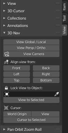
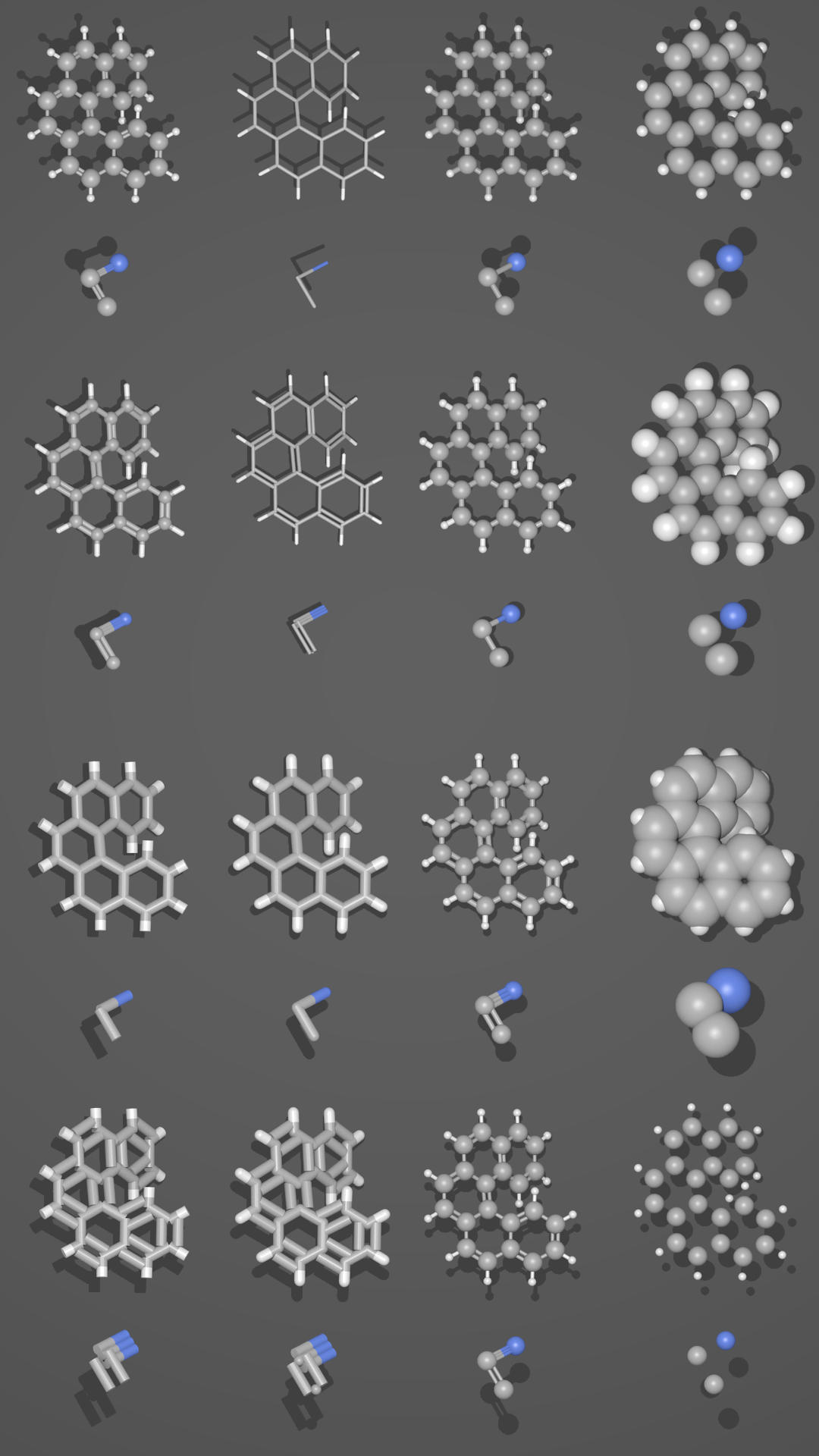 Different presentations of one and the same molecule.
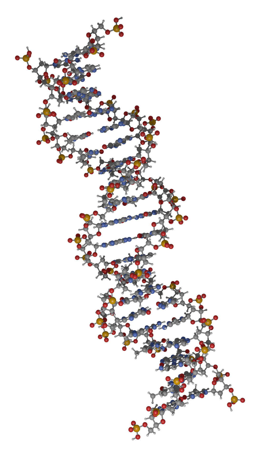 Part of a DNA molecule.
 Functionalized [5]helicene molecules on the NaCl(001) surface
(Clemens Barth et al. –
Functionalized [5]helicene molecules on the NaCl(001) surface
(Clemens Barth et al. –
 Solar cell structure to underline the properties of silicon nanocrystals deposited by pulsed spray system
(Mickael Lozac’h et al. –
Solar cell structure to underline the properties of silicon nanocrystals deposited by pulsed spray system
(Mickael Lozac’h et al. –
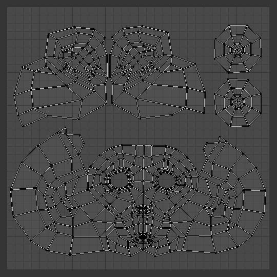 A UV layout in the UV Editor.
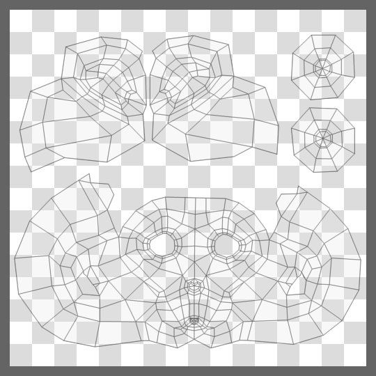 A UV layout in a paint program.
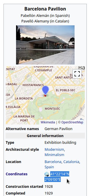 Copy the coordinates from Wikipedia.
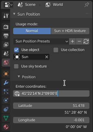 And paste them into Blender to have them parsed.
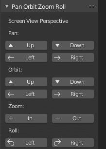
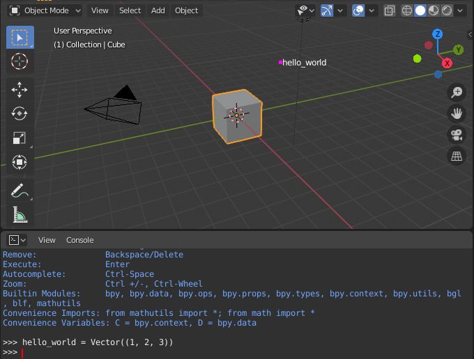
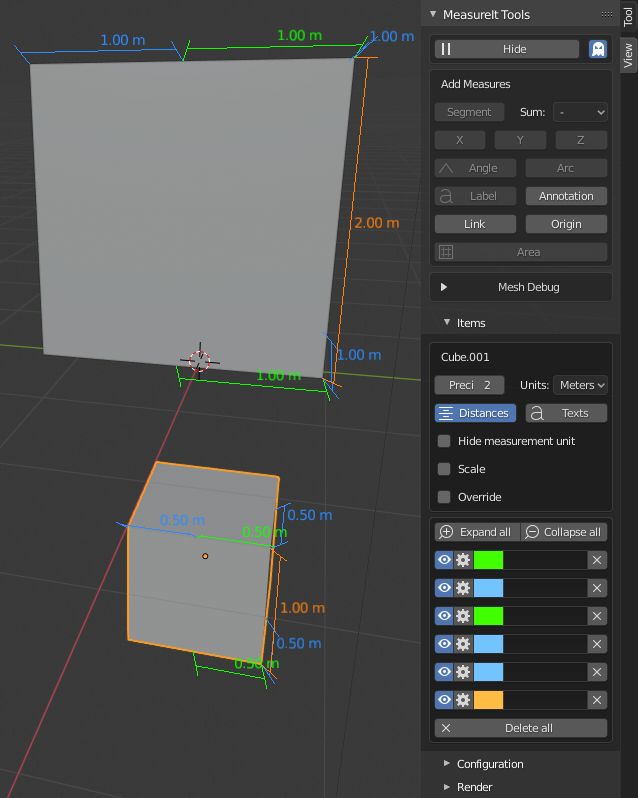
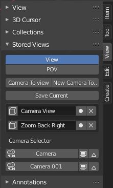
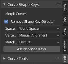
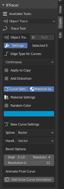


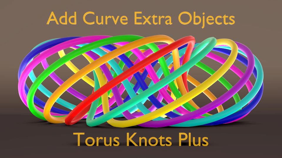
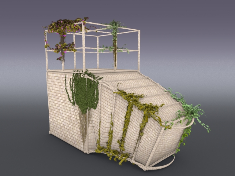
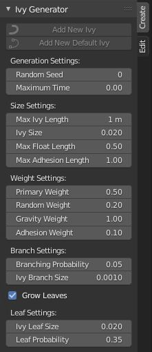
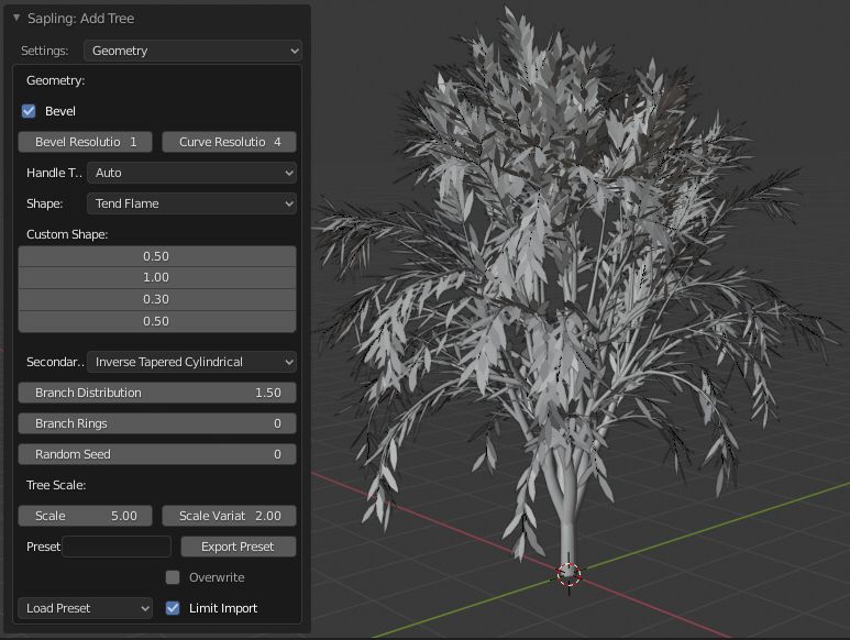
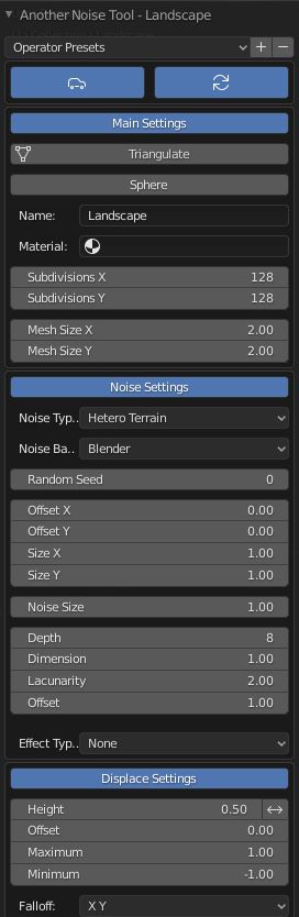
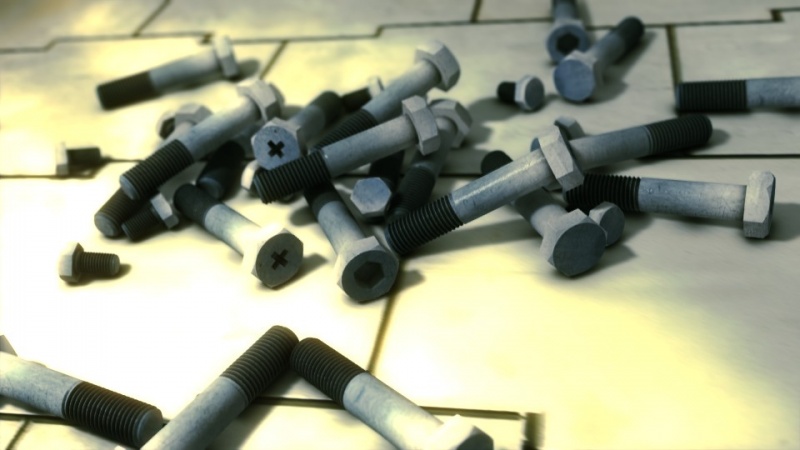
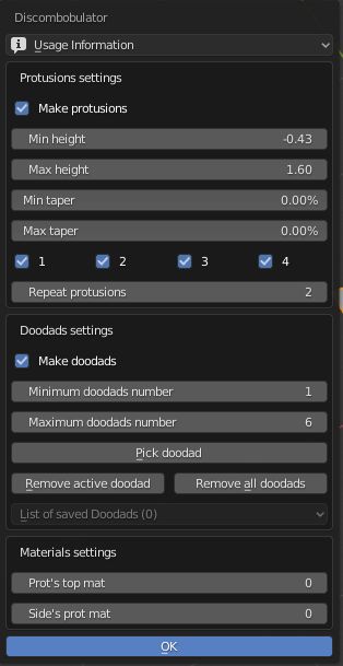
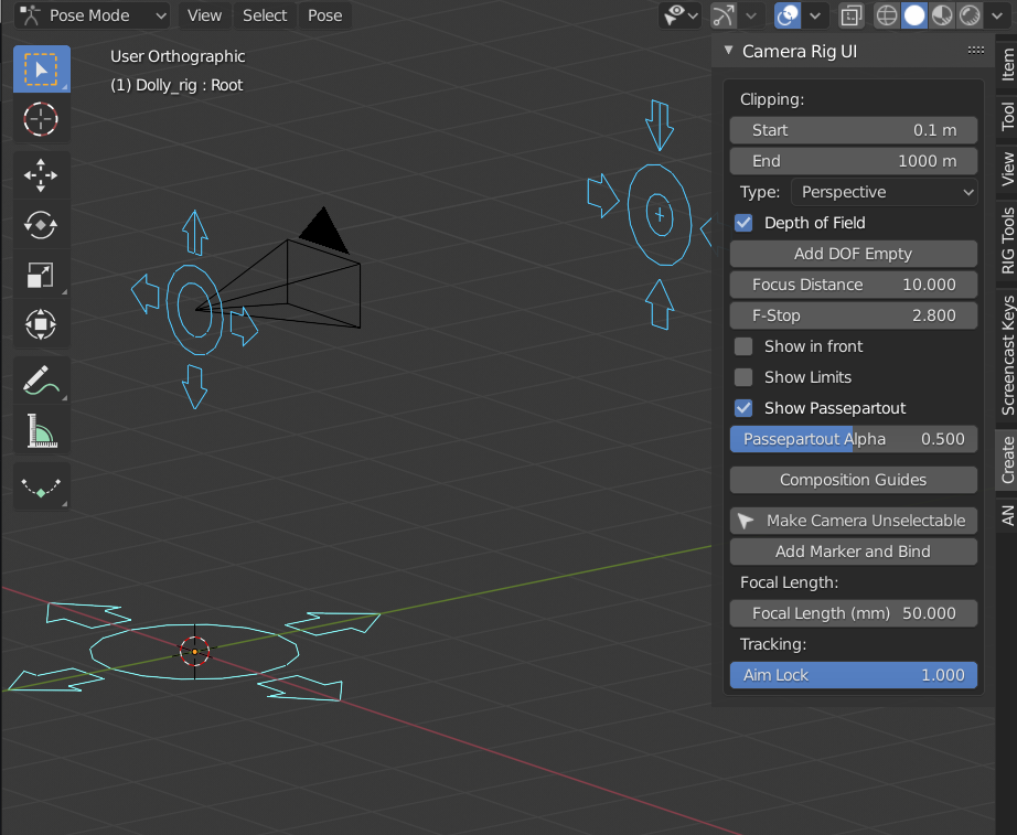 This script was designed to add some extended functionality to a camera by creating control rig
with custom shapes and UI to easily access the cameras settings from the 3D View.
This script was designed to add some extended functionality to a camera by creating control rig
with custom shapes and UI to easily access the cameras settings from the 3D View.
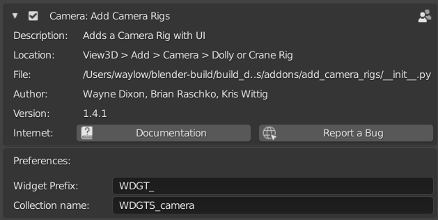
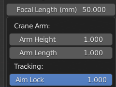
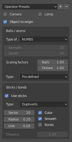
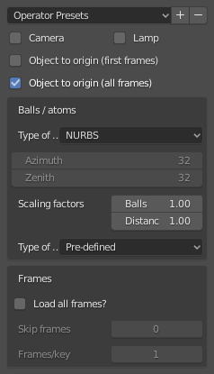
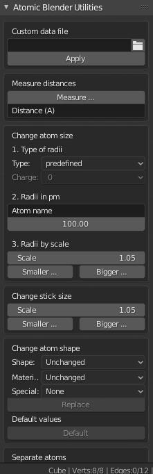
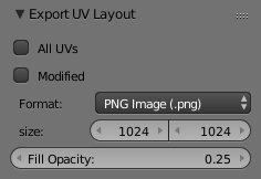
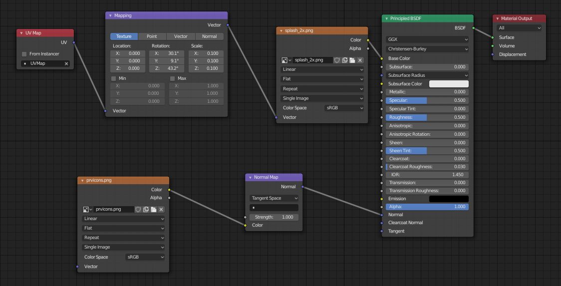
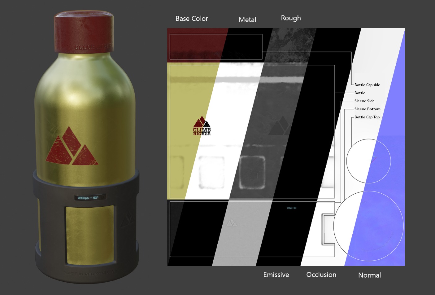
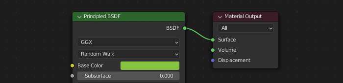
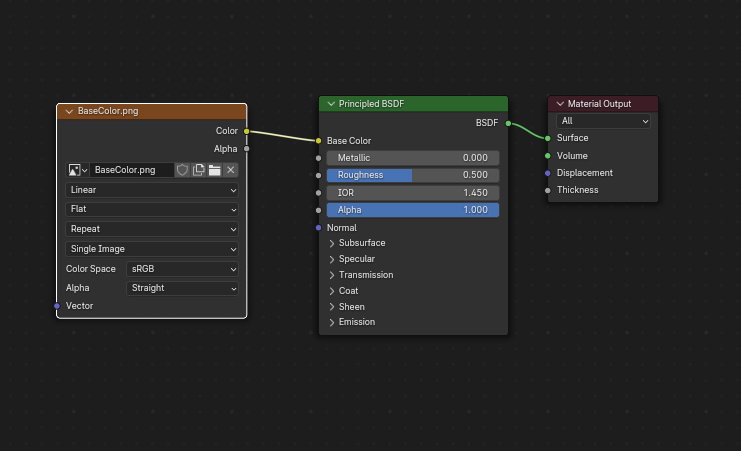
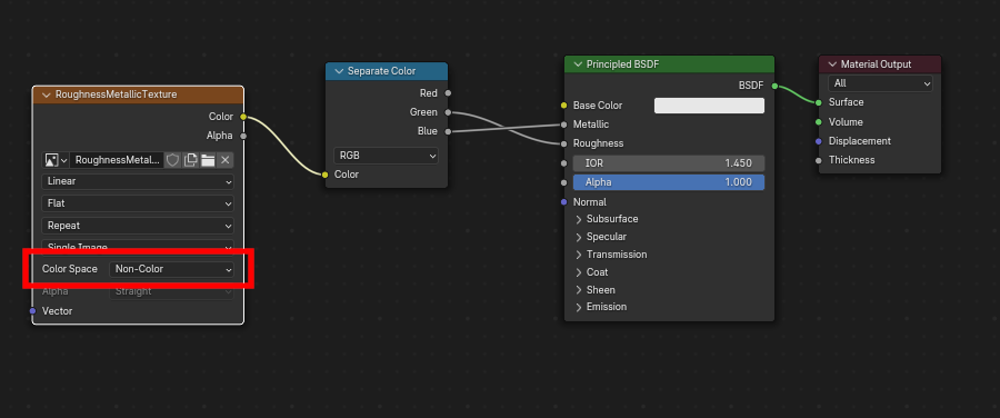
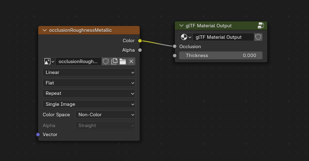
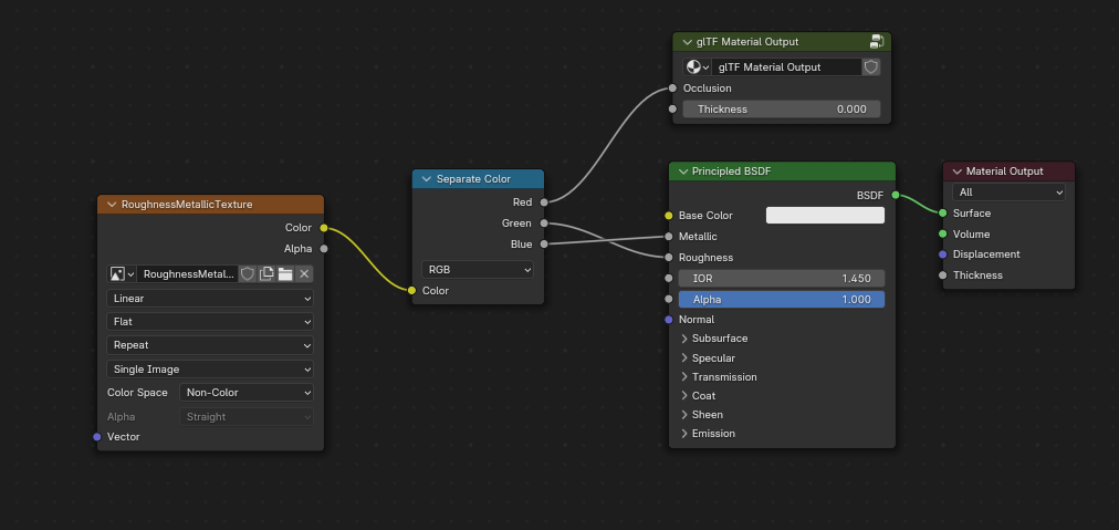
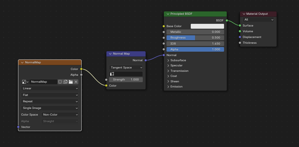
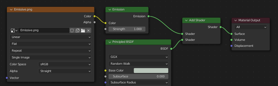
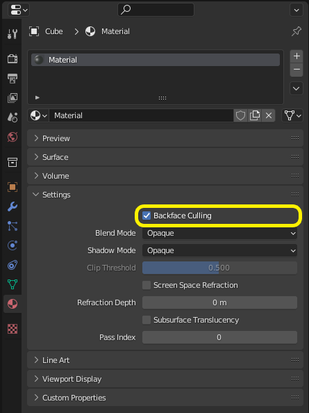
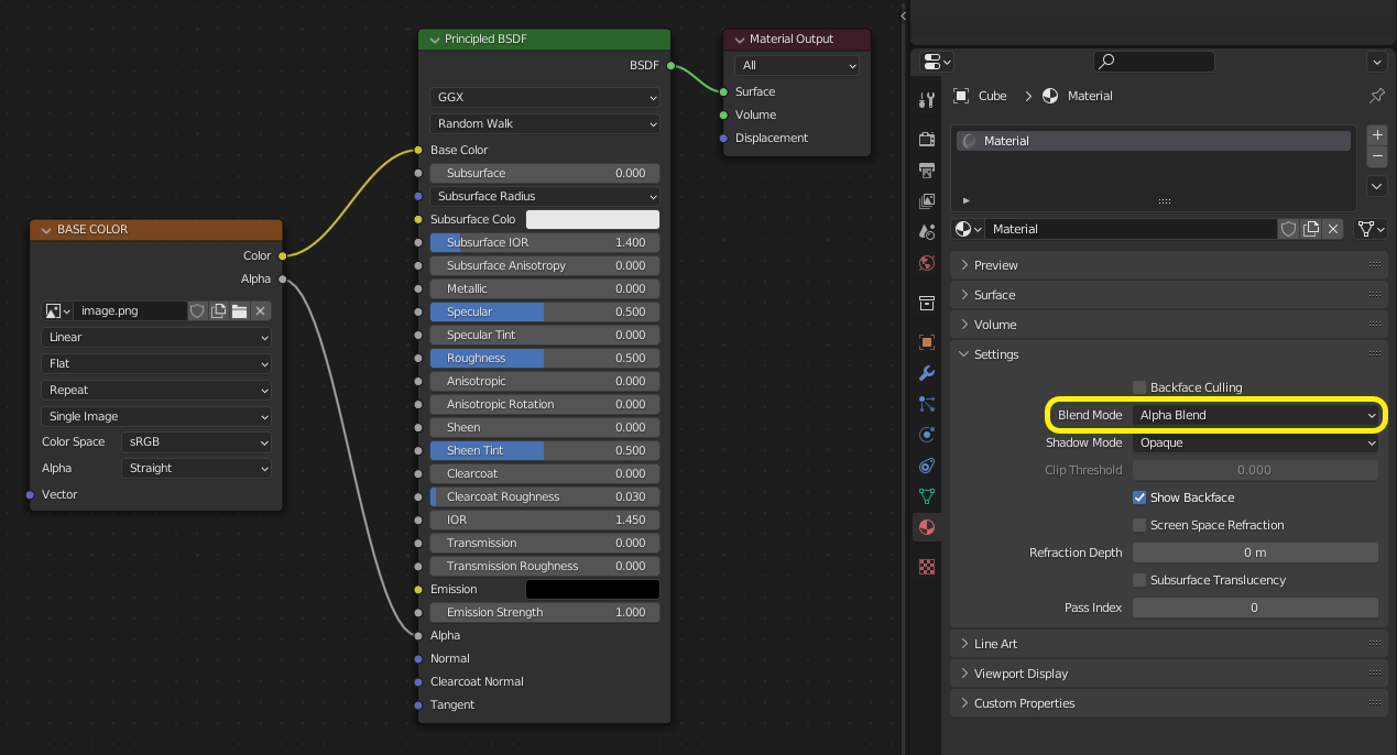
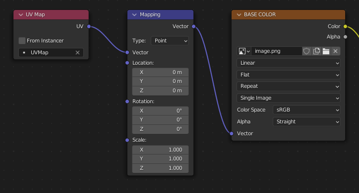
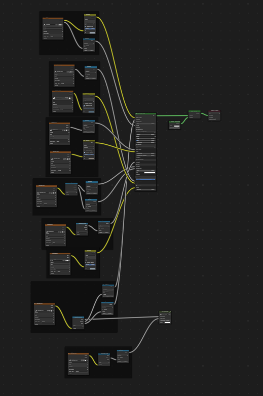

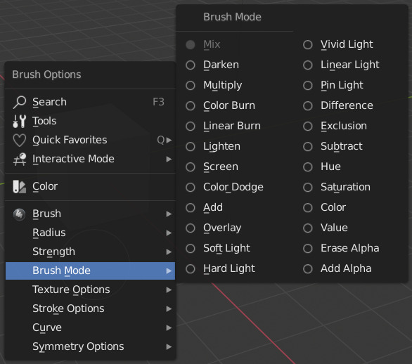 Reference
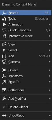 Dynamic Context Menu provides access to many of the menus found in the 3D View header.
It also packs a few features of its own, such as the Cursor menu.
Access Operator Search, Tools, Animation, Quick Favorites, Modifiers, Collections and more.
It is context sensitive for the 3D View’s modes and object sensitive based on object selected in Edit Mode.
This add-on pairs well with the
Dynamic Context Menu provides access to many of the menus found in the 3D View header.
It also packs a few features of its own, such as the Cursor menu.
Access Operator Search, Tools, Animation, Quick Favorites, Modifiers, Collections and more.
It is context sensitive for the 3D View’s modes and object sensitive based on object selected in Edit Mode.
This add-on pairs well with the