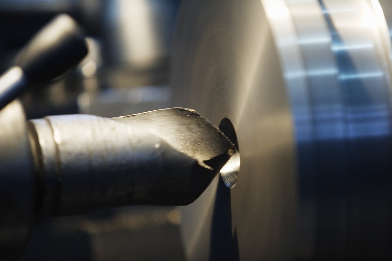
Getting Started with G-Code
Must Watch!
Getting Started with G-Code
Programming is a fundamental skill for all types of CNC machining, even as automation and new technology seem to be replacing programming tasks.
Every machinist still needs to understand how their programs and tools work.
Whether you're new to CNC programming and its most common language, g-code, or you've been writing code by scratch for years, CNC codes can still feel like a foreign language.
And to make things worse, every machine speaks a different dialect you have to understand.
Do you understand what they're saying? Here are the g-code basics you need to know to efficiently understand and write programs that produce high quality products.
What is G-Code?
G-code is a programming language for CNC that instructs machines where and how to move.
Most machines speak a different “dialect” of g-code, so the codes vary depending on type, make, and model.
Each machine comes with an instruction manual that shows that particular machine's code for a specific function.
G-code stands for “geometric code,” and follows some variation of the alpha numeric pattern:
N## G## X## Y## Z## F## S## T## M##
N: Line numberG: MotionX: Horizontal positionY: Vertical positionZ: DepthF: Feed rateS: Spindle speedT: Tool selectionM: Miscellaneous functionsI and J: Incremental center of an arcR: Radius of an arc
Alpha numeric codes are used for programming as they are a simple way to:
Define motion and function (G##)
Declare a position (X## Y## Z##)
Set a value (F## and/or S##)
Select an item (T##)
Switch something on and off (M##), such as coolant, spindles, indexing motion, axes locks, etc.
For example,
G01 X1 Y1 F20 T01 M03 S500
would generally indicate a linear feed move (G01) to the given XY position at feed rate of 20.
It is using Tool 1, and the spindle speed is 500.
Miscellaneous functions will vary from machine to machine, so in order to know what the m-code means, the machine's instruction manual will need to be referenced.
Machine Motion
Everything a machine can do is based on three basic types of motion:
Rapid move: a linear move to an XYZ position as fast as possible
Feed move: a linear move to an XYZ position at a defined feed rate
Circular move: a circular move at a defined feed rate
Every g-code tells the machine which variation of these basic motions to perform, and how to perform it.
X and Y are Cartesian coordinates for horizontal and vertical position, and Z represents the depth of the machine.
These alpha numerals will follow the motion/function command (G) to declare the position of the machine.
Next, F determines the feed rate (for feed moves or circular moves), while S determines the spindle speed.
T is used to select a tool.
Other alpha numerals used in programming might include I, J, and R, which have to do with arc centers and radii.
Miscellaneous Codes
The line of a program might also include m-codes, which are generally codes that tell a machine how to perform an action.
While not guaranteed to be the same across machines, some common, standard m-codes are:
M00: Program stop
M01: Optional program stop
M02: End of program
M03: Spindle on clockwise
M04: Spindle on counterclockwise
M05: Spindle stop
M06: Tool change
M08: Flood coolant on
M09: Flood coolant off
M30: End of program/return to start
M41: Spindle low gear range
M42: Spindle high gear range
Modality
Just like a light will stay on until it's turned off, g-code functions (on controllers that support modality) will remain active until they are deactivated by another code.
In other words, only one function can be active at any given time.
To deactivate a function, just select a new function.
 For example, say a code begins with a linear rapid move at X1 Y1 (G00 X1 Y1).
If the next function is another linear rapid move, it is not necessary to write G00 again.
All that is needed on the next line of code is the new position (say, X2 Y2) because the modal condition is the same.
Then, to change the function to a linear feed (G01), programming G01 on the following line would deactivate the linear rapid move and activate the linear feed.
Once a condition is set, it stays active until it is turned off or another condition overrides it.
For example, say a code begins with a linear rapid move at X1 Y1 (G00 X1 Y1).
If the next function is another linear rapid move, it is not necessary to write G00 again.
All that is needed on the next line of code is the new position (say, X2 Y2) because the modal condition is the same.
Then, to change the function to a linear feed (G01), programming G01 on the following line would deactivate the linear rapid move and activate the linear feed.
Once a condition is set, it stays active until it is turned off or another condition overrides it.
Canned Cycles
Canned cycles are a kind of modal condition that incorporate all the motions to complete a common task into one code.
 For example, oftentimes G81 is code for a basic drilling function.
In the case of basic drilling, the tool would have to be 1) moved to the starting point of the hole's location, 2) rapid to the clearance plane, 3) fed to the depth, and 4) rapid out.
That would be four lines of code in the program that would have to be repeated for every new drill position! With the canned cycle G81, only the hole locations need to be specified after activation.
Canned cycles like G81 significantly reduce the amount of code by incorporating multiple motions into one code.
For example, oftentimes G81 is code for a basic drilling function.
In the case of basic drilling, the tool would have to be 1) moved to the starting point of the hole's location, 2) rapid to the clearance plane, 3) fed to the depth, and 4) rapid out.
That would be four lines of code in the program that would have to be repeated for every new drill position! With the canned cycle G81, only the hole locations need to be specified after activation.
Canned cycles like G81 significantly reduce the amount of code by incorporating multiple motions into one code.
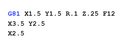 Some other common canned cycles exist for peck drilling, counter boring, and tapping.
Modal Code Groups
Modal code groups allow there to be multiple codes on a single line, but there can only be one code from each group on a line.
This is because codes within a group will override each other.
The modal groups for g-codes are:
Group 1 (motion): G00, G01, G02, G03, G80, G81, G82, G84, G85, G86, G87, G88, G89
Group 2 (plane selection – XY, YZ, ZX): G17, G18, G19
Group 3 (absolute/incremental mode): G90, G91
Group 5 (feed rate mode): G93, G94
Group 6 (units – inches/millimeters): G20, G21
Group 7 (cutter radius compensation – CRC): G40, G41, G42
Group 8 (tool length offset – TLO): G43, G49
Group 10 (return mode in canned cycles): G98, G99
Group 12 (work coordinate system selection – WCSS): G54, G55, G56, G57, G58, G59)
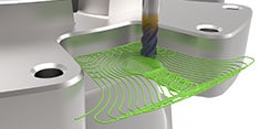
Postprocessors
A postprocessor is a translator that translates the calculated image of a toolpath on your computer screen into the language for a machine control.
You can create a post processor by searching for a sample program that aligns closely with your machine, and then amending the program to precisely fit your machine.
Before you can do this, you'll need to know:
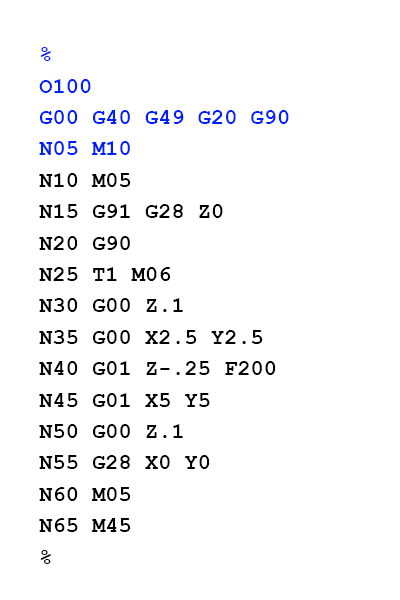
Get Started with G-Code
Ready to start using g-code to program your machines? Begin by reviewing your machine's unique coding chart.
Remember, every machine is a little different.
A Haas' code for a function might not be the same as an Anilam's code for that function.
You have to know which codes your specific machine uses for the tasks you want it to perform.
The program will often start with an initialization code (%), followed by a program number.
Then, there will be a line of safety codes.
Next will be a line for tool change.
This puts the appropriate tool in the machine and set the speed to be used.
The bulk of the program will then be the machine movements and positioning.
If using line numbering, it's a good idea to name each line in increments of at least five.
This way, if you need to add lines of code later, the lines will still be labelled in order.
When you've finished programming your g-code, you'll typically end the program with a series of functions that stop and reset the machine so it's ready for the next time.
G-Code Tips to Note
Some machines and controllers ignore spaces.
G01 X1 Y1 Z1 might mean the same thing as G01 X1Y1Z1.
The Z-axis is positive in the up direction.
Z1 will bring the tool up, while Z-1 will bring the tool down.
Your machine's g-code dialect will specify if a leading zero is necessary (as in G01, as opposed to G1).
The dialect will also determine if decimal points are always necessary (ex. G01 X1. Y1. Z0.5)
It's a good idea to run the sample programs that come in your machine manual before you try to run a big program.
Oftentimes, the sample programs do not work and you will need to note the issues and set your own benchmarks.
When used correctly, g-codes are an invaluable tool for CNC machinists, allowing you to take full advantage of your machine's capabilities.
And integrated CAM solutions continue to streamline the CNC coding process, so you don't have to program parts by hand using g-codes.
Producing high quality parts has never been faster.
G-code shouldn't be “all Greek” to you.
Even as automatic coding and other manufacturing advancements take shape, understanding CNC language will bridge the manufacturing borders that have been holding you back, helping you make the best products possible.
CNC G codes, M codes
Common G codes and M codes for CNC
Not all codes are available on all controls, and some controls have other codes.
See your machine manual for detailed explanations.
CNC G codes
Code Category Function Notes
G00 Motion Move in a straight line at rapids speed. XYZ of endpoint
G00 - Positioning at rapid speed; Mill and Lathe
G01 Motion Move in a straight line at last speed commanded by a (F)eedrate XYZ of endpoint
G01 - Linear interpolation (machining a straight line); Mill and Lathe
G02 Motion Clockwise circular arc at (F)eedrate XYZ of endpoint IJK relative to center R for radius
G02 - Circular interpolation clockwise (machining arcs); Mill and Lathe
G03 Motion Counter-clockwise circular arc at (F)eedrate XYZ of endpoint IJK relative to center R for radius
G03 - Circular interpolation, counter clockwise; Mill and Lathe
G04 Motion Dwell: Stop for a specified time. P for milliseconds X for seconds
G04 - Mill and Lathe, Dwell
G05 Motion FADAL Non-Modal Rapids
G09 Motion Exact stop check
G09 - Mill and Lathe, Exact stop
G10 Compensation Programmable parameter input
G10 - Setting offsets in the program; Mill and Lathe
G12 - Circular pocket milling, clockwise; Mill
G13 - Circular pocket milling, counterclockwise; Mill
G15 Coordinate Turn Polar Coordinates OFF, return to Cartesian Coordinates
G16 Coordinate Turn Polar Coordinates ON
G17 Coordinate Select X-Y plane
G17 - X-Y plane for arc machining; Mill and Lathe with live tooling
G18 Coordinate Select X-Z plane
G18 - Z-X plane for arc machining; Mill and Lathe with live tooling
G19 Coordinate Select Y-Z plane
G19 - Z-Y plane for arc machining; Mill and Lathe with live tooling
G20 Coordinate Program coordinates are inches
G20 - Inch units; Mill and Lathe
G21 Coordinate Program coordinates are mm
G21 - Metric units; Mill and Lathe
G27 Motion Reference point return check
G27 - Reference return check; Mill and Lathe
G28 Motion Return to home position
G28 - Automatic return through reference point; Mill and Lathe
G29 Motion Return from the reference position
G29 - Move to location through reference point; Mill and Lathe (slightly different for each machine)
G30 Motion Return to the 2nd, 3rd, and 4th reference point
G31 - Skip function; Mill and Lathe
G32 Canned Constant lead threading (like G01 synchronized with spindle)
G32 - Thread cutting; Lathe
G33 - Thread cutting; Mill
G40 Compensation Tool cutter compensation off (radius comp.)
G40 - Cancel diameter offset; Mill. Cancel tool nose offset; Lathe
G41 Compensation Tool cutter compensation left (radius comp.)
G41 - Cutter compensation left; Mill. Tool nose radius compensation left; Lathe
G42 Compensation Tool cutter compensation right (radius comp.)
G42 - Cutter compensation right; Mill. Tool nose radius compensation right; Lathe
G43 Compensation Apply tool length compensation (plus)
G43 - Tool length compensation; Mill
G44 Compensation Apply tool length compensation (minus)
G44 - Tool length compensation cancel; Mill (sometimes G49)
G49 Compensation Tool length compensation cancel
G50 Compensation Reset all scale factors to 1.0
G50 - Set coordinate system and maximum RPM; Lathe
G51 Compensation Turn on scale factors
G52 Coordinate Local workshift for all coordinate systems: add XYZ offsets
G52 - Local coordinate system setting; Mill and Lathe
G53 Coordinate Machine coordinate system (cancel work offsets)
G53 - Machine coordinate system setting; Mill and Lathe
G54 Coordinate Work coordinate system (1st Workpiece)
G54~G59 - Workpiece coordinate system settings #1 t0 #6; Mill and Lathe
G55 Coordinate Work coordinate system (2nd Workpiece)
G56 Coordinate Work coordinate system (3rd Workpiece)
G57 Coordinate Work coordinate system (4th Workpiece)
G58 Coordinate Work coordinate system (5th Workpiece)
G59 Coordinate Work coordinate system (6th Workpiece)
G61 Other Exact stop check mode
G61 - Exact stop check; Mill and Lathe
G62 Other Automatic corner override
G63 Other Tapping mode
G64 Other Best speed path
G65 Other Custom macro simple call
G65 - Custom macro call; Mill and Lathe
G68 Coordinate Coordinate System Rotation
G69 Coordinate Cancel Coordinate System Rotation
G70 - Finish cycle; Lathe
G71 - Rough turning cycle; Lathe
G72 - Rough facing cycle; Lathe
G73 Canned High speed drilling cycle (small retract)
G73 - Chip break drilling cycle; Mill
G73 - Irregular rough turning cycle; Lathe
G74 Canned Left hand tapping cycle
G74 - Face grooving or chip break drilling; Lathe
G74 - Left hand tapping; Mill
G75 - OD groove pecking; Lathe
G76 Canned Fine boring cyle
G76 - Fine boring cycle; Mill
G76 - Threading cycle; Lathe
G80 Canned Cancel canned cycle
G80 - Cancel cycles; Mill and Lathe
G81 Canned Simple drilling cycle
G81 - Drill cycle; Mill and Lathe
G82 Canned Drilling cycle with dwell (counterboring)
G82 - Drill cycle with dwell; Mill
G83 Canned Peck drilling cycle (full retract),Peck drilling cycle; Mill
G84 Canned Tapping cycle; Mill and Lathe
G85 Canned Boring canned cycle, no dwell, feed out, Bore in, bore out; Mill and Lathe
G86 Canned Boring canned cycle, spindle stop, rapid out, Bore in, rapid out; Mill and Lathe
G87 Canned Back boring canned cycle, Back boring cycle; Mill
G88 Canned Boring canned cycle, spindle stop, manual out
G89 Canned Boring canned cycle, dwell, feed out
G90 Coordinate Absolute programming of XYZ (type B and C systems), Absolute programming
G90.1 Coordinate Absolute programming IJK (type B and C systems)
G91 Coordinate Incremental programming of XYZ (type B and C systems), Incremental programming
G91.1 Coordinate Incremental programming IJK (type B and C systems)
G92 Coordinate Offset coordinate system and save parameters
G92 (alternate) Motion Clamp of maximum spindle speed S G92.1 Coordinate Cancel offset and zero parameters
G92 - Reposition origin point; Mill,Thread cutting cycle; Lathe
G92.2 Coordinate Cancel offset and retain parameters
G92.3 Coordinate Offset coordinate system with saved parameters
G94 Motion Units per minute feed mode. Units in inches or mm.,Per minute feed; Mill
G95 Motion Units per revolution feed mode. Units in inches or mm.,Per revolution feed; Mill
G96 Motion Constant surface speed control; Lathe
G97 Motion Cancel constant surface speed, Constant surface speed cancel
G98 Canned Return to initial Z plane after canned cycle, Per minute feed; Lathe
G99 Canned Return to initial R plane after canned cycle, Per revolution feed; Lathe
CNC M Codes
Code Category Function Notes
M00 Program Stop (non-optional); Mill and Lathe
M01 Optional Stop: Operator Selected to Enable, Optional program stop; Lathe and Mill
M02 End of Program, Program end; Lathe and Mill
M03 Spindle ON (CW Rotation); Lathe and Mill
M04 Spindle ON (CCW Rotation); Lathe and Mill
M05 Spindle Stop, Spindle off; Lathe and Mill
M06 Toolchange; Mill
M07 Mist Coolant ON
M08 Flood Coolant ON, Coolant on; Lathe and Mill
M09 Coolant off; Lathe and Mill
M10 Chuck or rotary table clamp; Lathe and Mill
M11 Chuck or rotary table clamp off; Lathe and Mill
M17 FADAL subroutine return
M19 Orient spindle; Lathe and Mill
M29 Rigid Tapping Mode on Fanuc Controls
M30 End of Program, Rewind and Reset Modes, Program end, return to start; Lathe and Mill
M97 Haas-Style Subprogram Call, Local sub-routine call; Lathe and Mill
M98 Sub-program call; Lathe and Mill
M99 Return from Subprogram, End of sub program; Lathe and Mill